El sistema de calefacción autónomo de mi apartamento tiene un termostato ambiental inalámbrico disponible comercialmente. El sistema, por supuesto, funciona sin él: el termostato fue comprado para ahorrar consumo de gas y aumentar la comodidad.
La cosa es muy útil, pero, en mi opinión, algo anticuada. Se decidió ensamblar algo similar a un termostato comprado, agregando, para empezar, una configuración más conveniente y una conexión a Internet al diseño del termostato.
Lo que sucedió como resultado, sigue leyendo. Espero, además de mí, que el proyecto sea interesante para otros.
Conocido
Características y especificaciones:
- La conexión entre los nodos del termostato se realiza por aire a una frecuencia de radio.
- Durante el día, el termostato mantiene constantes tres puntos de ajuste de temperatura.
- La configuración del termostato (programa de trabajo, parámetros de límite de aire, otros) se configura de forma remota a través de Wi-Fi desde el formulario en el navegador.
- El termostato incluye la función de un monitor de calidad del aire con medición de temperatura, nivel de dióxido de carbono y humedad del aire.
- El termostato está equipado con un reloj de tiempo real con sincronización de reloj con el servidor de hora exacto a través de Internet.
- El termostato se controla desde la interfaz de la aplicación móvil Blynk. Además, la aplicación Blynk acepta y muestra los resultados de las mediciones de temperatura, CO2 y humedad del aire.
- El termostato se desconecta automáticamente en ausencia de Wi-Fi.
- Los mensajes se envían desde el termostato al correo electrónico si la temperatura, el contenido de CO 2 o la humedad del aire están fuera de los valores umbral.
- En el termostato, además de la temperatura, es posible mantener los parámetros de aire medidos restantes dentro de los límites especificados.
- Al final de la temporada de calefacción, el termostato no tendrá que estar oculto: el monitor de calidad del aire permanecerá en funcionamiento con el envío de mensajes al correo y al reloj.
El termostato consta de dos dispositivos. En el primer dispositivo, se genera una señal de control para el dispositivo de calefacción o sistema de calefacción y se transmite al segundo dispositivo, llamemos a este dispositivo un analizador. El segundo dispositivo, recibe la señal, la descifra y controla la fuente de calor, deja que sea un contactor. La conexión entre el analizador y el contactor es inalámbrica, en la frecuencia de radio.
Asamblea
Para ensamblar el dispositivo, necesitará componentes, una lista de los cuales y su costo estimado a los precios del sitio web AliExpress se muestran en la tabla.
| Componente | Precio, $ |
| analizador |
| Tarjeta wifi NodeMCU CP2102 ESP8266 | 2,53 |
| Sensor de temperatura y humedad DHT22 | 2,34 |
| Sensor de contenido de CO2 MH Z-19 | 18.50 |
| Reloj RTC DS3231 | 1.00 |
| Pantalla OLED LCD azul 0.96 "I2C 128x64 | 1,95 |
| Módulo RF 433MHz, transmisor (precio del kit: transmisor, receptor) | 0,99 |
| Convertidor de nivel lógico de 4 canales 3.3V-5V (convertidor de capa lógica) | 0.28 |
| Estabilizador de voltaje LM7805 (10 piezas) | 0,79 |
| AC100-240V 50 / 60Hz DC12V 2A adaptador | 10.70 |
| Placa de desarrollo (fibra de vidrio), contactos, etc. | 2,00 |
| contactor |
| Módulo Arduino Pro Mini 5V | 1,45 |
| Módulo RF 433MHz (receptor) | - |
| Módulo de relé de 2 canales | 0,98 |
| Adaptador AC-DC HLK-PM01 | 4.29 |
| Placa de desarrollo (fibra de vidrio), contactos, etc. | 2,00 |
| Total (aproximadamente): | 50 |
Si planea ensamblar un termostato con dimensiones mínimas, entonces necesita reemplazar el convertidor de nivel lógico de 4 canales con un módulo de relé de 2 canales y 2 canales con uno de 1 canal.
Ambos dispositivos están ensamblados en tableros de prototipos de fibra de vidrio. Montaje - montado. Los módulos se instalan en los paneles, ensamblados a partir del "peine" de contactos. Este enfoque tiene varias ventajas: los componentes se desmontan fácilmente, la instalación de una nueva versión del boceto se cambia fácilmente y, por último, no es visible en el cuerpo hecho en casa cómo se hizo.
Las antenas del transmisor y el receptor tienen un cable de 17.3 cm de largo. La mayor potencia del transmisor y las antenas más simples proporcionan una comunicación confiable dentro del departamento.
Analizador

El cerebro del analizador es el controlador ESP8266 en la placa del módulo NodeMCU CP2102. Recibe señales de sensores y genera señales de control para el transmisor y la pantalla.

Al instalar el sensor DHT22 en la placa, la temperatura medida es 1.5 ... 2 ° C más alta que la real (¡incluso sin la carcasa!). Por lo tanto, debe colocar el sensor de temperatura alejado de elementos con alta disipación de calor LM7805 y NodeMCU CP2102. Además, sería bueno instalar el regulador de voltaje LM7805 en el radiador y definitivamente es necesario garantizar una buena convección del aire en el caso de bajar la temperatura y reducir su error de medición. Otra opción para deshacerse del error es mover el sensor DHT22 más allá del volumen del cuerpo; esta opción es más simple y la elegí.
Hay muchas quejas en Internet sobre la baja precisión del DHT22. Hoy existe una alternativa: sensores de temperatura y humedad más modernos HTU21D, Si7021, SHT21.
Se suministra una tensión de CC de 12 V desde el adaptador de CA / CC al analizador. Además, el estabilizador de voltaje constante LM7805 genera un voltaje de 5V. El voltaje de la fuente de alimentación del transmisor es de 12V. Al probar el dispositivo, cuando el analizador y el contactor están cerca del escritorio, el analizador se puede alimentar desde el puerto USB de la computadora al suministrar voltaje al módulo NodeMCU CP2102 con un cable USB estándar: microUSB. La tensión de alimentación del NodeMCU CP2102 y MH Z-19 es de 5V, la fuente de alimentación a los nodos restantes del circuito (3,3V) forma el estabilizador del módulo NodeMCU CP2102.
El sensor de temperatura y humedad DHT22 está conectado al terminal D6 del módulo NodeMCU CP2102. El reloj DC3231 y la pantalla de 0.96 "están conectados al ESP8266 (en el módulo NodeMCU CP2102) a través de la interfaz de dos hilos I2C, y los pines Tx, Rx del sensor de contenido de CO2 MH Z-19 están conectados a los pines Rx, Tx ESP8266, respectivamente. La señal se transmite al transmisor desde el NodeMCU CP2102 a través del convertidor niveles lógicos, que convierten la señal de NodeMCU CP2102 con una amplitud de aproximadamente 3.3V en una señal cuya amplitud está cerca del voltaje de alimentación del transmisor de 12V.
Si usa una batería en lugar de una batería en el módulo del reloj, no olvide romper el circuito de carga de la batería, de lo contrario, la batería se hinchará después de unas pocas semanas de trabajar bajo voltaje. Con una precisión de reloj autoalimentado de 2 segundos / año, está garantizado.
El boceto del analizador para cargar en el ESP8266 está debajo del spoiler.
bosquejo analizador #include <FS.h> #include <Arduino.h> #include <ESP8266WiFi.h> //https://github.com/esp8266/Arduino // Wifi Manager #include <DNSServer.h> #include <ESP8266WebServer.h> #include <WiFiManager.h> //https://github.com/tzapu/WiFiManager //e-mail #include <ESP8266WiFiMulti.h> //https://github.com/esp8266/Arduino/blob/master/libraries/ESP8266WiFi/src/ESP8266WiFiMulti.h #include <ESP8266HTTPClient.h> ESP8266WiFiMulti WiFiMulti; char address[64] {"e-mail"}; //e-mail, address // HTTP requests #include <ESP8266HTTPClient.h> // OTA updates #include <ESP8266httpUpdate.h> // Blynk #include <BlynkSimpleEsp8266.h> // Debounce #include <Bounce2.h> //https://github.com/thomasfredericks/Bounce2 // JSON #include <ArduinoJson.h> //https://github.com/bblanchon/ArduinoJson //clock #include <pgmspace.h> #include <TimeLib.h> #include <WiFiUdp.h> #include <Wire.h> #include <RtcDS3231.h> //https://github.com/Makuna/Rtc RtcDS3231<TwoWire> Rtc(Wire); #define countof(a) (sizeof(a) / sizeof(a[0])) //timer #include <SimpleTimer.h> SimpleTimer timer; // unsigned int timerCO2; // MH-Z19 unsigned int timerBl; // Blynk unsigned int timerMail; // // GPIO Defines #define I2C_SDA 4 // D2 - OLED #define I2C_SCL 5 // D1 - OLED #define DHTPIN 12 //D6 cp2102 // Humidity/Temperature #include <DHT.h> #define DHTTYPE DHT22 // DHT 22 DHT dht(DHTPIN, DHTTYPE); #define mySerial Serial // Use U8g2 for i2c OLED Lib #include <SPI.h> #include <U8g2lib.h> U8G2_SSD1306_128X64_NONAME_F_SW_I2C u8g2(U8G2_R0, I2C_SCL, I2C_SDA, U8X8_PIN_NONE); byte x {0}; byte y {0}; // Blynk token char blynk_token[33] {"Blynk token"}; //Transmitter #include <RCSwitch.h> RCSwitch transmitter = RCSwitch(); unsigned long TimeTransmitMax; // / // Setup Wifi connection WiFiManager wifiManager; // Network credentials String ssid {"am-5108"}; String pass {"vb" + String(ESP.getFlashChipId())}; //flag for saving data bool shouldSaveConfig = false; // float t {-100}; // int h {-1}; // int co2 {-1}; // co2 float Chs = 0.2; // () (: 0.1( ) - 0.4 ( )) char Tmx[]{"25.0"}, Hmn[]{"35"}, Cmx[]{"1000"}, tZ[]{"2.0"}; // t, h co2, . float Cmax, Tmax, Hmin, tZone; char Temperature0[]{"20.0"}, Temperature1[]{"22.0"}, Temperature2[]{"19.0"};// float TemperaturePoint0, TemperaturePoint1, TemperaturePoint2, TemperaturePoint1Mn, TemperaturePoint2Mn, TemperaturePoint1Pl, TemperaturePoint2Pl; float TemperaturePointA0 = 21.0; // char Hour1[]{"6"}, Hour2[]{"22"}; // , float HourPoint1, HourPoint2; float MinPoint1 = 0, MinPoint2 = 0; int n, j, m; // , int progr = 0; // int timeSummerWinter = 0; // (1)/(0) int a = 1; // : 1 - , 2 - bool buttonBlynk = true; // (true)/(falce) V(10) Blynk //NTP, clock uint8_t hh,mm,ss; //containers for current time char time_r[9]; char date_r[12]; // NTP Servers: //static const char ntpServerName[] = "us.pool.ntp.org"; static const char ntpServerName[] = "time.nist.gov"; WiFiUDP Udp; unsigned int localPort = 2390; // local port to listen for UDP packets time_t getNtpTime(); void digitalClockDisplay(); void printDigits(int digits); void sendNTPpacket(IPAddress &address); void digitalClockDisplay() { // digital clock display of the time Serial.print(hour()); printDigits(minute()); printDigits(second()); Serial.print(" "); Serial.print(day()); Serial.print("."); Serial.print(month()); Serial.print("."); Serial.print(year()); Serial.println(); } void printDigits(int digits) { // utility for digital clock display: prints preceding colon and leading 0 Serial.print(":"); if (digits < 10) Serial.print('0'); Serial.print(digits); } //NTP code const int NTP_PACKET_SIZE = 48; // NTP time is in the first 48 bytes of message byte packetBuffer[NTP_PACKET_SIZE]; //buffer to hold incoming & outgoing packets time_t getNtpTime() { int tZoneI; tZoneI = (int)tZone; IPAddress ntpServerIP; // NTP server's ip address while (Udp.parsePacket() > 0) ; // discard any previously received packets Serial.println("Transmit NTP Request"); // get a random server from the pool WiFi.hostByName(ntpServerName, ntpServerIP); Serial.print(ntpServerName); Serial.print(": "); Serial.println(ntpServerIP); sendNTPpacket(ntpServerIP); uint32_t beginWait = millis(); while (millis() - beginWait < 1500) { int size = Udp.parsePacket(); if (size >= NTP_PACKET_SIZE) { Serial.println("Receive NTP Response"); Udp.read(packetBuffer, NTP_PACKET_SIZE); // read packet into the buffer unsigned long secsSince1900; // convert four bytes starting at location 40 to a long integer secsSince1900 = (unsigned long)packetBuffer[40] << 24; secsSince1900 |= (unsigned long)packetBuffer[41] << 16; secsSince1900 |= (unsigned long)packetBuffer[42] << 8; secsSince1900 |= (unsigned long)packetBuffer[43]; return secsSince1900 - 2208988800UL + tZoneI * SECS_PER_HOUR + timeSummerWinter * SECS_PER_HOUR; //tZoneI } } Serial.println("No NTP Response (:-()"); return 0; // return 0 if unable to get the time } // send an NTP request to the time server at the given address void sendNTPpacket(IPAddress &address) { // set all bytes in the buffer to 0 memset(packetBuffer, 0, NTP_PACKET_SIZE); // Initialize values needed to form NTP request // (see URL above for details on the packets) packetBuffer[0] = 0b11100011; // LI, Version, Mode packetBuffer[1] = 0; // Stratum, or type of clock packetBuffer[2] = 6; // Polling Interval packetBuffer[3] = 0xEC; // Peer Clock Precision // 8 bytes of zero for Root Delay & Root Dispersion packetBuffer[12] = 49; packetBuffer[13] = 0x4E; packetBuffer[14] = 49; packetBuffer[15] = 52; // all NTP fields have been given values, now // you can send a packet requesting a timestamp: Udp.beginPacket(address, 123); //NTP requests are to port 123 Udp.write(packetBuffer, NTP_PACKET_SIZE); Udp.endPacket(); } void synchronClockA() { WiFiManager wifiManager; Rtc.Begin(); Serial.print("IP number assigned by DHCP is "); Serial.println(WiFi.localIP()); Serial.println("Starting UDP"); Udp.begin(localPort); Serial.print("Local port: "); Serial.println(Udp.localPort()); Serial.println("waiting for sync"); setSyncProvider(getNtpTime); if(timeStatus() != timeNotSet){ digitalClockDisplay(); Serial.println("here is another way to set rtc"); time_t t = now(); char date_0[12]; snprintf_P(date_0, countof(date_0), PSTR("%s %02u %04u"), monthShortStr(month(t)), day(t), year(t)); Serial.println(date_0); char time_0[9]; snprintf_P(time_0, countof(time_0), PSTR("%02u:%02u:%02u"), hour(t), minute(t), second(t)); Serial.println(time_0); Serial.println("Now its time to set up rtc"); RtcDateTime compiled = RtcDateTime(date_0, time_0); // printDateTime(compiled); Serial.println(""); if (!Rtc.IsDateTimeValid()) { // Common Cuases: // 1) first time you ran and the device wasn't running yet // 2) the battery on the device is low or even missing Serial.println("RTC lost confidence in the DateTime!"); // following line sets the RTC to the date & time this sketch was compiled // it will also reset the valid flag internally unless the Rtc device is // having an issue } Rtc.SetDateTime(compiled); RtcDateTime now = Rtc.GetDateTime(); if (now < compiled) { Serial.println("RTC is older than compile time! (Updating DateTime)"); Rtc.SetDateTime(compiled); } else if (now > compiled) { Serial.println("RTC is newer than compile time. (this is expected)"); } else if (now == compiled) { Serial.println("RTC is the same as compile time! (not expected but all is fine)"); } // never assume the Rtc was last configured by you, so // just clear them to your needed state Rtc.Enable32kHzPin(false); Rtc.SetSquareWavePin(DS3231SquareWavePin_ModeNone); } } void synchronClock() { Rtc.Begin(); wifiManager.autoConnect(ssid.c_str(), pass.c_str()); while (WiFi.status() != WL_CONNECTED) { delay(500); Serial.print("."); } Serial.println(" "); Serial.print("IP number assigned by DHCP is "); Serial.println(WiFi.localIP()); Serial.println("Starting UDP"); Udp.begin(localPort); Serial.print("Local port: "); Serial.println(Udp.localPort()); Serial.println("waiting for sync"); setSyncProvider(getNtpTime); if(timeStatus() != timeNotSet){ digitalClockDisplay(); Serial.println("here is another way to set rtc"); time_t t = now(); char date_0[12]; snprintf_P(date_0, countof(date_0), PSTR("%s %02u %04u"), monthShortStr(month(t)), day(t), year(t)); Serial.println(date_0); char time_0[9]; snprintf_P(time_0, countof(time_0), PSTR("%02u:%02u:%02u"), hour(t), minute(t), second(t)); Serial.println(time_0); Serial.println("Now its time to set up rtc"); RtcDateTime compiled = RtcDateTime(date_0, time_0); Serial.println(""); if (!Rtc.IsDateTimeValid()) { // Common Cuases: // 1) first time you ran and the device wasn't running yet // 2) the battery on the device is low or even missing Serial.println("RTC lost confidence in the DateTime!"); // following line sets the RTC to the date & time this sketch was compiled // it will also reset the valid flag internally unless the Rtc device is // having an issue } Rtc.SetDateTime(compiled); RtcDateTime now = Rtc.GetDateTime(); if (now < compiled) { Serial.println("RTC is older than compile time! (Updating DateTime)"); Rtc.SetDateTime(compiled); } else if (now > compiled) { Serial.println("RTC is newer than compile time. (this is expected)"); } else if (now == compiled) { Serial.println("RTC is the same as compile time! (not expected but all is fine)"); } // never assume the Rtc was last configured by you, so // just clear them to your needed state Rtc.Enable32kHzPin(false); Rtc.SetSquareWavePin(DS3231SquareWavePin_ModeNone); } } void Clock(){ RtcDateTime now = Rtc.GetDateTime(); //Print RTC time to Serial Monitor hh = now.Hour(); mm = now.Minute(); ss = now.Second(); sprintf(date_r, "%d.%d.%d", now.Day(), now.Month(), now.Year()); if (mm < 10) sprintf(time_r, "%d:0%d", hh, mm); else sprintf(time_r, "%d:%d", hh, mm); Serial.println(date_r); Serial.println(time_r); } //callback notifying the need to save config void saveConfigCallback() { Serial.println("Should save config"); shouldSaveConfig = true; } void factoryReset() { Serial.println("Resetting to factory settings"); wifiManager.resetSettings(); SPIFFS.format(); ESP.reset(); } void printString(String str) { Serial.println(str); } void readCO2() { static byte cmd[9] = {0xFF,0x01,0x86,0x00,0x00,0x00,0x00,0x00,0x79}; // byte response[9]; byte crc = 0; while (mySerial.available())mySerial.read(); // UART memset(response, 0, 9);// mySerial.write(cmd,9);// CO2 mySerial.readBytes(response, 9);// 9 // crc = 0; for (int i = 1; i <= 7; i++) { crc += response[i]; } crc = ((~crc)+1); { // CRC if ( !(response[0] == 0xFF && response[1] == 0x86 && response[8] == crc) ) { Serial.println("CRC error"); } else { // CO2 co2 = (((unsigned int) response[2])<<8) + response[3]; Serial.println("CO2: " + String(co2) + "ppm"); } } } void sendMeasurements() { float t1 {-100}; int h1 {-1}, i; // Temperature t1 = dht.readTemperature(); if ((t1 > -1) and (t1 < 100)) t = t1; Serial.println("T: " + String(t) + "C"); // Humidity h1 = dht.readHumidity(); if ((h1 > -1) and (h1 < 100)) h = h1; Serial.println("H: " + String(h) + "%"); // CO2 readCO2(); } void sendToBlynk(){ Blynk.virtualWrite(V1, t); Blynk.virtualWrite(V2, h); Blynk.virtualWrite(V3, co2); Blynk.virtualWrite(V4, TemperaturePoint0); } void noData() { u8g2.setFont(u8g2_font_9x18_mf); x = 48; y = 40; u8g2.drawStr(x, y, "***"); } void drawOn() { float TemperatureP0; char Online_ch[]{" Online"}; TemperatureP0 = TemperaturePoint0 - Chs; dtostrf(TemperatureP0, 4, 1, Temperature0); // float char String Temperature0_i; Temperature0_i = String(Temperature0); char Temperature0_i_m [16]; Temperature0_i.toCharArray(Temperature0_i_m, 16); u8g2.clearBuffer(); String Temperature0_p; String onl1 = "OnLine T<"; Temperature0_p = onl1 + Temperature0_i_m; char Temperature0_p_m [16]; Temperature0_p.toCharArray(Temperature0_p_m, 16); String Tmx_i; Tmx_i = String(Tmx); char Tmx_i_m [16]; Tmx_i.toCharArray(Tmx_i_m, 16); u8g2.clearBuffer(); String Tmx_p; String onl2 = "OnLine T>"; Tmx_p = onl2 + Tmx_i_m; char Tmx_p_m [16]; Tmx_p.toCharArray(Tmx_p_m, 16); String Cmx_i; Cmx_i = String(Cmx); char Cmx_i_m [16]; Cmx_i.toCharArray(Cmx_i_m, 16); u8g2.clearBuffer(); String Cmx_p; String onl3 = "OnL CO2>"; Cmx_p = onl3 + Cmx_i_m; char Cmx_p_m [16]; Cmx_p.toCharArray(Cmx_p_m, 16); String Hmn_i; Hmn_i = String(Hmn); char Hmn_i_m [16]; Hmn_i.toCharArray(Hmn_i_m, 16); u8g2.clearBuffer(); String Hmn_p; String onl4 = "OnLine H<"; Hmn_p = onl4 + Hmn_i_m; char Hmn_p_m [16]; Hmn_p.toCharArray(Hmn_p_m, 16); //string 3 u8g2.setFont(u8g2_font_9x18_mf); x = 0; y = 64; u8g2.drawStr(x, y, Online_ch); if ((hh>=HourPoint1) and (hh<=HourPoint2) and (t<TemperatureP0)) u8g2.drawStr(x, y, Temperature0_p_m); else if (t > Tmax) u8g2.drawStr(x, y, Tmx_p_m); else if (co2 > Cmax) u8g2.drawStr(x, y, Cmx_p_m); else if (h < Hmin) u8g2.drawStr(x, y, Hmn_p_m); switch((millis() / 100) % 4) { // Temperature case 0: { String info_t; String paramT; String tmpr = "T("; String grad = "C):"; const char degree {176}; paramT = tmpr + degree + grad; char paramT_m [12]; paramT.toCharArray(paramT_m, 12); info_t = String(t); char info_t_m [12]; info_t.toCharArray(info_t_m, 5); //string 1 u8g2.setFont(u8g2_font_9x18_mf); x = 16; y = u8g2.getAscent() - u8g2.getDescent(); u8g2.drawStr(x, y, paramT_m); //string 2 if ((t > -100) and (t < 100)) { u8g2.setFont(u8g2_font_inb24_mf); x = (128 - u8g2.getStrWidth(info_t_m))/2; y = y + 2 + u8g2.getAscent() - u8g2.getDescent(); u8g2.drawStr(x, y, info_t_m); } else noData(); } break; //Humidity case 1: { String info_h; info_h = String(h); char info_h_m [12]; info_h.toCharArray(info_h_m, 12); //string 1 u8g2.setFont(u8g2_font_9x18_mf); x = 16; y = u8g2.getAscent() - u8g2.getDescent(); u8g2.drawStr(x, y, "H(%):"); //string 2 if ((h > -1) and (h < 100)){ u8g2.setFont(u8g2_font_inb24_mf); x = (128 - u8g2.getStrWidth(info_h_m))/2; y = y + 2 + u8g2.getAscent() - u8g2.getDescent(); u8g2.drawStr(x, y, info_h_m); } else noData(); } break; //CO2 case 2: { String info_co2; info_co2 = String(co2); char info_co2_m [12]; info_co2.toCharArray(info_co2_m, 12); //string 1 u8g2.setFont(u8g2_font_9x18_mf); x = 8; y = u8g2.getAscent() - u8g2.getDescent(); u8g2.drawStr(x, y, "CO2(ppm):"); //string 2 if ((co2 > -1) and (co2 <= 2000)) { u8g2.setFont(u8g2_font_inb24_mf); x = (128 - u8g2.getStrWidth(info_co2_m))/2; y = y + 2 + u8g2.getAscent() - u8g2.getDescent(); u8g2.drawStr(x, y, info_co2_m); } else noData(); } break; //time, date case 3: { //string 1 u8g2.setFont(u8g2_font_9x18_mf); x = (128 - u8g2.getStrWidth(date_r))/2; y = u8g2.getAscent() - u8g2.getDescent(); u8g2.drawStr(x, y, date_r); //string 2 u8g2.setFont(u8g2_font_inb24_mf); x = (128 - u8g2.getStrWidth(time_r))/2; y = y + 2 + u8g2.getAscent() - u8g2.getDescent(); u8g2.drawStr(x, y, time_r); } break; } u8g2.sendBuffer(); } void drawOff() { float TemperatureP0A; char OffLine_ch[]{"Offline Tst=21"}; TemperatureP0A = TemperaturePointA0 - Chs; // dtostrf(TemperatureP0A, 4, 1, TemperaturePointA0); // float char String TemperaturePointA0_i; TemperaturePointA0_i = String(TemperaturePointA0); char TemperaturePointA0_i_m [16]; TemperaturePointA0_i.toCharArray(TemperaturePointA0_i_m, 16); u8g2.clearBuffer(); String TemperaturePointA0_p; String onl1 = "Offline T<"; TemperaturePointA0_p = onl1 + TemperaturePointA0_i_m; char TemperaturePointA0_p_m [16]; TemperaturePointA0_p.toCharArray(TemperaturePointA0_p_m, 16); //string 3 u8g2.setFont(u8g2_font_9x18_mf); x = 0; y = 64; u8g2.drawStr(x, y, OffLine_ch); if (t<TemperatureP0A) u8g2.drawStr(x, y, TemperaturePointA0_p_m); switch((millis() / 100) % 4) { // Temperature case 0: { String info_t; String paramT; String tmpr = "T("; String grad = "C):"; const char degree {176}; paramT = tmpr + degree + grad; char paramT_m [12]; paramT.toCharArray(paramT_m, 12); info_t = String(t); char info_t_m [12]; info_t.toCharArray(info_t_m, 5); //string 1 u8g2.setFont(u8g2_font_9x18_mf); x = 16; y = u8g2.getAscent() - u8g2.getDescent(); u8g2.drawStr(x, y, paramT_m); //string 2 if ((t > -100) and (t < 100)) { u8g2.setFont(u8g2_font_inb24_mf); x = (128 - u8g2.getStrWidth(info_t_m))/2; y = y + 2 + u8g2.getAscent() - u8g2.getDescent(); u8g2.drawStr(x, y, info_t_m); } else noData(); } break; //Humidity case 1: { String info_h; info_h = String(h); char info_h_m [12]; info_h.toCharArray(info_h_m, 12); //string 1 u8g2.setFont(u8g2_font_9x18_mf); x = 16; y = u8g2.getAscent() - u8g2.getDescent(); u8g2.drawStr(x, y, "H(%):"); //string 2 if ((h > -1) and (h < 100)){ u8g2.setFont(u8g2_font_inb24_mf); x = (128 - u8g2.getStrWidth(info_h_m))/2; y = y + 2 + u8g2.getAscent() - u8g2.getDescent(); u8g2.drawStr(x, y, info_h_m); } else noData(); } break; //CO2 case 2: { String info_co2; info_co2 = String(co2); char info_co2_m [12]; info_co2.toCharArray(info_co2_m, 12); //string 1 u8g2.setFont(u8g2_font_9x18_mf); x = 8; y = u8g2.getAscent() - u8g2.getDescent(); u8g2.drawStr(x, y, "CO2(ppm):"); //string 2 if ((co2 > -1) and (co2 <= 2000)) { u8g2.setFont(u8g2_font_inb24_mf); x = (128 - u8g2.getStrWidth(info_co2_m))/2; y = y + 2 + u8g2.getAscent() - u8g2.getDescent(); u8g2.drawStr(x, y, info_co2_m); } else noData(); } break; //time, date case 3: { //string 1 u8g2.setFont(u8g2_font_9x18_mf); x = (128 - u8g2.getStrWidth(date_r))/2; y = u8g2.getAscent() - u8g2.getDescent(); u8g2.drawStr(x, y, date_r); //string 2 u8g2.setFont(u8g2_font_inb24_mf); x = (128 - u8g2.getStrWidth(time_r))/2; y = y + 2 + u8g2.getAscent() - u8g2.getDescent(); u8g2.drawStr(x, y, time_r); } break; } u8g2.sendBuffer(); } void drawOffBlynk() { float TemperatureP0; char OffBlynk_ch[]{" OffBlynk"}; TemperatureP0 = TemperaturePoint0 - Chs; dtostrf(TemperatureP0, 4, 1, Temperature0); // float char String Temperature0_i; Temperature0_i = String(Temperature0); char Temperature0_i_m [16]; Temperature0_i.toCharArray(Temperature0_i_m, 16); u8g2.clearBuffer(); String Temperature0_p; String onl1 = "OffBL T<"; Temperature0_p = onl1 + Temperature0_i_m; char Temperature0_p_m [16]; Temperature0_p.toCharArray(Temperature0_p_m, 16); String Tmx_i; Tmx_i = String(Tmx); char Tmx_i_m [16]; Tmx_i.toCharArray(Tmx_i_m, 16); u8g2.clearBuffer(); String Tmx_p; String onl2 = "OffBL T>"; Tmx_p = onl2 + Tmx_i_m; char Tmx_p_m [16]; Tmx_p.toCharArray(Tmx_p_m, 16); String Cmx_i; Cmx_i = String(Cmx); char Cmx_i_m [16]; Cmx_i.toCharArray(Cmx_i_m, 16); u8g2.clearBuffer(); String Cmx_p; String onl3 = "OnL CO2>"; Cmx_p = onl3 + Cmx_i_m; char Cmx_p_m [16]; Cmx_p.toCharArray(Cmx_p_m, 16); String Hmn_i; Hmn_i = String(Hmn); char Hmn_i_m [16]; Hmn_i.toCharArray(Hmn_i_m, 16); u8g2.clearBuffer(); String Hmn_p; String onl4 = "OffBL H<"; Hmn_p = onl4 + Hmn_i_m; char Hmn_p_m [16]; Hmn_p.toCharArray(Hmn_p_m, 16); //string 3 u8g2.setFont(u8g2_font_9x18_mf); x = 0; y = 64; u8g2.drawStr(x, y, OffBlynk_ch); if ((hh>=HourPoint1) and (hh<=HourPoint2) and (t<TemperatureP0)) u8g2.drawStr(x, y, Temperature0_p_m); else if (t > Tmax) u8g2.drawStr(x, y, Tmx_p_m); else if (co2 > Cmax) u8g2.drawStr(x, y, Cmx_p_m); else if (h < Hmin) u8g2.drawStr(x, y, Hmn_p_m); switch((millis() / 100) % 4) { // Temperature case 0: { String info_t; String paramT; String tmpr = "T("; String grad = "C):"; const char degree {176}; paramT = tmpr + degree + grad; char paramT_m [12]; paramT.toCharArray(paramT_m, 12); info_t = String(t); char info_t_m [12]; info_t.toCharArray(info_t_m, 5); //string 1 u8g2.setFont(u8g2_font_9x18_mf); x = 16; y = u8g2.getAscent() - u8g2.getDescent(); u8g2.drawStr(x, y, paramT_m); //string 2 if ((t > -100) and (t < 100)) { u8g2.setFont(u8g2_font_inb24_mf); x = (128 - u8g2.getStrWidth(info_t_m))/2; y = y + 2 + u8g2.getAscent() - u8g2.getDescent(); u8g2.drawStr(x, y, info_t_m); } else noData(); } break; //Humidity case 1: { String info_h; info_h = String(h); char info_h_m [12]; info_h.toCharArray(info_h_m, 12); //string 1 u8g2.setFont(u8g2_font_9x18_mf); x = 16; y = u8g2.getAscent() - u8g2.getDescent(); u8g2.drawStr(x, y, "H(%):"); //string 2 if ((h > -1) and (h < 100)){ u8g2.setFont(u8g2_font_inb24_mf); x = (128 - u8g2.getStrWidth(info_h_m))/2; y = y + 2 + u8g2.getAscent() - u8g2.getDescent(); u8g2.drawStr(x, y, info_h_m); } else noData(); } break; //CO2 case 2: { String info_co2; info_co2 = String(co2); char info_co2_m [12]; info_co2.toCharArray(info_co2_m, 12); //string 1 u8g2.setFont(u8g2_font_9x18_mf); x = 8; y = u8g2.getAscent() - u8g2.getDescent(); u8g2.drawStr(x, y, "CO2(ppm):"); //string 2 if ((co2 > -1) and (co2 <= 2000)) { u8g2.setFont(u8g2_font_inb24_mf); x = (128 - u8g2.getStrWidth(info_co2_m))/2; y = y + 2 + u8g2.getAscent() - u8g2.getDescent(); u8g2.drawStr(x, y, info_co2_m); } else noData(); } break; //time, date case 3: { //string 1 u8g2.setFont(u8g2_font_9x18_mf); x = (128 - u8g2.getStrWidth(date_r))/2; y = u8g2.getAscent() - u8g2.getDescent(); u8g2.drawStr(x, y, date_r); //string 2 u8g2.setFont(u8g2_font_inb24_mf); x = (128 - u8g2.getStrWidth(time_r))/2; y = y + 2 + u8g2.getAscent() - u8g2.getDescent(); u8g2.drawStr(x, y, time_r); } break; } u8g2.sendBuffer(); } void drawBoot(String msg = "Loading...") { u8g2.clearBuffer(); u8g2.setFont(u8g2_font_9x18_mf); x = (128 - u8g2.getStrWidth(msg.c_str())) / 2; y = 32 + u8g2.getAscent() / 2; u8g2.drawStr(x, y, msg.c_str()); u8g2.sendBuffer(); } void drawConnectionDetails(String ssid, String pass, String url) { String msg {""}; u8g2.clearBuffer(); msg = "Connect to WiFi:"; u8g2.setFont(u8g2_font_7x13_mf); x = (128 - u8g2.getStrWidth(msg.c_str())) / 2; y = u8g2.getAscent() - u8g2.getDescent(); u8g2.drawStr(x, y, msg.c_str()); msg = "net: " + ssid; x = (128 - u8g2.getStrWidth(msg.c_str())) / 2; y = y + 1 + u8g2.getAscent() - u8g2.getDescent(); u8g2.drawStr(x, y, msg.c_str()); msg = "pw: "+ pass; x = (128 - u8g2.getStrWidth(msg.c_str())) / 2; y = y + 1 + u8g2.getAscent() - u8g2.getDescent(); u8g2.drawStr(x, y, msg.c_str()); msg = "Open browser:"; x = (128 - u8g2.getStrWidth(msg.c_str())) / 2; y = y + 1 + u8g2.getAscent() - u8g2.getDescent(); u8g2.drawStr(x, y, msg.c_str()); // URL // u8g2.setFont(u8g2_font_6x12_mf); x = (128 - u8g2.getStrWidth(url.c_str())) / 2; y = y + 1 + u8g2.getAscent() - u8g2.getDescent(); u8g2.drawStr(x, y, url.c_str()); u8g2.sendBuffer(); } bool loadConfigS(){ Blynk.config(address); Serial.print("e-mail: "); Serial.println( address ); Blynk.config(Tmx); Serial.print("T max: "); Serial.println( Tmx ); Blynk.config(Cmx); Serial.print("CO2 max: "); Serial.println( Cmx ); Blynk.config(Temperature0); Serial.print("Temperature 0: "); Serial.println( Temperature0 ); Blynk.config(Temperature1); Serial.print("Temperature1: "); Serial.println( Temperature1 ); Blynk.config(Temperature2); Serial.print("Temperature2: "); Serial.println( Temperature2 ); Blynk.config(Hmn); Serial.print("H min: "); Serial.println( Hmn ); Blynk.config(Hour1); Serial.print("Hour 1: "); Serial.println( Hour1 ); Blynk.config(Hour2); Serial.print("Hour 2: "); Serial.println( Hour2 ); Blynk.config(tZ); Serial.print("Time Zone: "); Serial.println( tZ ); Blynk.config(blynk_token, "blynk-cloud.com", 8442); Serial.print("token: " ); Serial.println( blynk_token ); } bool loadConfig() { Serial.println("Load config..."); File configFile = SPIFFS.open("/config.json", "r"); if (!configFile) { Serial.println("Failed to open config file"); return false; } size_t size = configFile.size(); if (size > 1024) { Serial.println("Config file size is too large"); return false; } // Allocate a buffer to store contents of the file. std::unique_ptr<char[]> buf(new char[size]); // We don't use String here because ArduinoJson library requires the input // buffer to be mutable. If you don't use ArduinoJson, you may as well // use configFile.readString instead. configFile.readBytes(buf.get(), size); StaticJsonBuffer<200> jsonBuffer; JsonObject &json = jsonBuffer.parseObject(buf.get()); if (!json.success()) { Serial.println("Failed to parse config file"); return false; } // Save parameters strcpy(blynk_token, json["blynk_token"]); strcpy(address, json["address"]); strcpy(Tmx, json["Tmx"]); strcpy(Cmx, json["Cmx"]); strcpy(Temperature0, json["Temperature0"]); strcpy(Temperature1, json["Temperature1"]); strcpy(Temperature2, json["Temperature2"]); strcpy(Hmn, json["Hmn"]); strcpy(Hour1, json["Hour1"]); strcpy(Hour2, json["Hour2"]); strcpy(tZ, json["tZ"]); } void configModeCallback (WiFiManager *wifiManager) { String url {"http://192.168.4.1"}; printString("Connect to WiFi:"); printString("net: " + ssid); printString("pw: "+ pass); printString("Open browser:"); printString(url); printString("to setup device"); drawConnectionDetails(ssid, pass, url); } void setupWiFi() { //set config save notify callback wifiManager.setSaveConfigCallback(saveConfigCallback); // Custom parameters WiFiManagerParameter custom_tZ("tZ", "Time Zone", tZ, 5); wifiManager.addParameter(&custom_tZ); WiFiManagerParameter custom_Temperature0("Temperature0", "Temperature 0", Temperature0, 5); wifiManager.addParameter(&custom_Temperature0); WiFiManagerParameter custom_Hour1("Hour1", "Hour 1", Hour1, 5); wifiManager.addParameter(&custom_Hour1); WiFiManagerParameter custom_Temperature1("Temperature1", "Temperature 1", Temperature1, 5); wifiManager.addParameter(&custom_Temperature1); WiFiManagerParameter custom_Hour2("Hour2", "Hour 2", Hour2, 5); wifiManager.addParameter(&custom_Hour2); WiFiManagerParameter custom_Temperature2("Temperature2", "Temperature 2", Temperature2, 5); wifiManager.addParameter(&custom_Temperature2); WiFiManagerParameter custom_Cmx("Cmx", "Cmax", Cmx, 7); wifiManager.addParameter(&custom_Cmx); WiFiManagerParameter custom_Hmn("Hmn", "Hmin", Hmn, 5); wifiManager.addParameter(&custom_Hmn); WiFiManagerParameter custom_Tmx("Tmx", "Tmax", Tmx,5); wifiManager.addParameter(&custom_Tmx); WiFiManagerParameter custom_address("address", "E-mail", address, 64); wifiManager.addParameter(&custom_address); WiFiManagerParameter custom_blynk_token("blynk_token", "Blynk Token", blynk_token, 34); wifiManager.addParameter(&custom_blynk_token); wifiManager.setAPCallback(configModeCallback); wifiManager.setTimeout(180); if (!wifiManager.autoConnect(ssid.c_str(), pass.c_str())) { a++; Serial.println("mode OffLINE :("); loadConfigS(); synchronClockA(); } //save the custom parameters to FS if (shouldSaveConfig) { Serial.println("saving config"); DynamicJsonBuffer jsonBuffer; JsonObject &json = jsonBuffer.createObject(); json["blynk_token"] = custom_blynk_token.getValue(); json["address"] = custom_address.getValue(); json["Tmx"] = custom_Tmx.getValue(); json["Cmx"] = custom_Cmx.getValue(); json["Temperature0"] = custom_Temperature0.getValue(); json["Temperature1"] = custom_Temperature1.getValue(); json["Temperature2"] = custom_Temperature2.getValue(); json["Hmn"] = custom_Hmn.getValue(); json["Hour1"] = custom_Hour1.getValue(); json["Hour2"] = custom_Hour2.getValue(); json["tZ"] = custom_tZ.getValue(); File configFile = SPIFFS.open("/config.json", "w"); if (!configFile) { Serial.println("failed to open config file for writing"); } json.printTo(Serial); json.printTo(configFile); configFile.close(); //end save } //if you get here you have connected to the WiFi Serial.println("WiFi connected"); Serial.print("IP address: "); Serial.println(WiFi.localIP()); } BLYNK_WRITE(V10) { if (param.asInt() == 1) { buttonBlynk = true; Blynk.virtualWrite(V10, HIGH); drawBoot("Thermo ON"); } else { buttonBlynk = false; Blynk.virtualWrite(V10, LOW); drawBoot("Thermo OFF"); } } void mailer() { // wait for WiFi connection if((WiFiMulti.run() == WL_CONNECTED)) { HTTPClient http; Serial.print("[HTTP] begin...\n"); http.begin("http://skorovoda.in.ua/php/aqm42.php?mymail="+String(address)+"&t="+String(t) +"&h="+String(h)+"&co2="+String(co2)+"&ID="+String(ESP.getChipId())); Serial.print("[HTTP] GET...\n"); // start connection and send HTTP header int httpCode = http.GET(); // httpCode will be negative on error if(httpCode > 0) { // HTTP header has been send and Server response header has been handled Serial.printf("[HTTP] GET... code: %d\n", httpCode); // file found at server if(httpCode == HTTP_CODE_OK) { String payload = http.getString(); Serial.println(payload); } } else { Serial.printf("[HTTP] GET... failed, error: %s\n", http.errorToString(httpCode).c_str()); } http.end(); } } void HystTemperatureA() { float TemperaturePointA0Mn, TemperaturePointA0Pl; TemperaturePointA0Mn = TemperaturePointA0-Chs; TemperaturePointA0Pl = TemperaturePointA0+Chs; if (t<TemperaturePointA0Mn) { if (millis() - TimeTransmitMax > 120000){ TimeTransmitMax = millis(); transmitter.send(B11111110, 8); Serial.println ("t<TemperaturePointA0Mn Thermostat ON"); } } else if (millis() - TimeTransmitMax > 120000) { TimeTransmitMax = millis(); transmitter.send(B10000000, 8); Serial.println ("t>TemperaturePointA0Mn Thermostat OFF"); } if (t<TemperaturePointA0Pl) { if (millis() - TimeTransmitMax > 120000){ TimeTransmitMax = millis(); transmitter.send(B11111110, 8); Serial.println ("t<TemperaturePointA0Pl Thermostat ON"); } } else if (millis() - TimeTransmitMax > 120000) { TimeTransmitMax = millis(); transmitter.send(B10000000, 8); Serial.println ("t>TemperaturePointA0Pl Thermostat OFF"); } } void HystTemperature() { float TemperaturePoint0Mn, TemperaturePoint0Pl; TemperaturePoint0Mn = TemperaturePoint0-Chs; TemperaturePoint0Pl = TemperaturePoint0+Chs; if (t<TemperaturePoint0Mn) { if (millis() - TimeTransmitMax > 120000){ TimeTransmitMax = millis(); transmitter.send(B11111110, 8); Serial.println ("t<TemperaturePoint0Mn Thermostat ON"); } } else if (millis() - TimeTransmitMax > 120000) { TimeTransmitMax = millis(); transmitter.send(B10000000, 8); Serial.println ("t>TemperaturePoint0Mn Thermostat OFF"); } if (t<TemperaturePoint0Pl) { if (millis() - TimeTransmitMax > 120000){ TimeTransmitMax = millis(); transmitter.send(B11111110, 8); Serial.println ("t<TemperaturePoint0Pl Thermostat ON"); } } else if (millis() - TimeTransmitMax > 120000) { TimeTransmitMax = millis(); transmitter.send(B10000000, 8); Serial.println ("t>TemperaturePoint0Pl Thermostat OFF"); } } void TransmitterA(){ transmitter.send(B10101010, 8); //B10101010 - HystTemperatureA(); } void Transmitter(){ transmitter.send(B10101010, 8); //B10101010 - if (n>=24) n = 0; if (m>=60) m = 0; progr = 0; if ((hh >= HourPoint1) and (hh < HourPoint2)){ progr = 1; if (mm >= MinPoint1) progr = 1; if (mm < MinPoint2) progr = 1; } else if (hh >= HourPoint2) { progr = 2; if (mm >= MinPoint2) progr = 2; } if (buttonBlynk==true) { Serial.println ("BLynk: "); if (progr == 0) { TemperaturePoint0 = TemperaturePoint0; HystTemperature(); Serial.println (": t = " + String(TemperaturePoint0)); } else if (progr == 1) { TemperaturePoint0 = TemperaturePoint1; HystTemperature(); Serial.println (": t = " + String(TemperaturePoint0)); } else if (progr == 2){ TemperaturePoint0 = TemperaturePoint2; HystTemperature(); Serial.println (": t = " + String(TemperaturePoint0)); } } else { transmitter.send(B10000000, 8); Serial.println ("BLynk: "); } if (co2 > Cmax) { transmitter.send(B11111101, 8); Serial.println("co2 > Cmax"); } else transmitter.send(B00000010, 8); if (h < Hmin) { transmitter.send(B11111011, 8); Serial.println("h < Hmin"); } else transmitter.send(B00000100, 8); if (t > Tmax) { transmitter.send(B11110111, 8); Serial.println("t > Tmax"); } else transmitter.send(B00001000, 8); } void connectBlynk(){ if(String(blynk_token)== "Blynk token"){ drawBoot("OFFBLYNK!"); delay (3000); } else { drawBoot("Connect. Blynk"); Serial.println("Connecting to blynk..."); while (Blynk.connect() == false) { delay(500); Serial.println("Connecting to blynk..."); } } } void setup() { // factoryReset(); // RAM mySerial.begin(9600); Serial.begin(115200); transmitter.enableTransmit(2); u8g2.begin(); // drawBoot("Loading..."); // if (!SPIFFS.begin()) { Serial.println("Failed to mount file system"); ESP.reset(); } // drawBoot("Connect. WiFi"); setupWiFi(); timerCO2 = timer.setInterval(15000, readCO2); buttonBlynk = true; if(a == 1){ // Load config drawBoot("Load Config"); if (!loadConfig()) { Serial.println("Failed to load config"); factoryReset(); } else { Serial.println("Config loaded"); } Blynk.config(address); Serial.print("e-mail: "); Serial.println(address); Blynk.config(Tmx); Serial.print("T max: "); Serial.println(Tmx); Blynk.config(Cmx); Serial.print("CO2 max: "); Serial.println(Cmx); Blynk.config(Temperature0); Serial.print("Temperature 0: "); Serial.println(Temperature0); Blynk.config(Temperature1); Serial.print("Temperature1: "); Serial.println(Temperature1); Blynk.config(Temperature2); Serial.print("Temperature2: "); Serial.println(Temperature2); Blynk.config(Hmn); Serial.print("H min: "); Serial.println(Hmn); Blynk.config(Hour1); Serial.print("Hour 1: "); Serial.println(Hour1); Blynk.config(Hour2); Serial.print("Hour 2: "); Serial.println(Hour2); Blynk.config(tZ); Serial.print("Time Zone: "); Serial.println(tZ); Blynk.config(blynk_token, "blynk-cloud.com", 8442); Serial.print("token: " ); Serial.println(blynk_token); // char float Tmax = atof (Tmx); Cmax = atof (Cmx); TemperaturePoint0 = atof (Temperature0); TemperaturePoint1 = atof (Temperature1); TemperaturePoint2 = atof (Temperature2); Hmin = atof (Hmn); HourPoint1 = atof (Hour1); HourPoint2 = atof (Hour2); tZone = atof (tZ); // drawBoot("Clock synchr."); synchronClock(); // timerCO2 = timer.setInterval(15000, readCO2); timerBl = timer.setInterval(5000, sendToBlynk); connectBlynk(); // Blynk Blynk.virtualWrite(V10, HIGH); // V10 buttonBlynk = true; } } void loop(){ if (a == 2) { Serial.println(":( OffLINE"); timer.run(); Clock(); sendMeasurements(); TransmitterA(); drawOff(); delay(1000); } else if (a == 1) { Serial.println(":) OnLINE"); timer.run(); Clock(); Blynk.run(); BLYNK_WRITE(V10); Transmitter(); sendMeasurements(); if(String(blynk_token) == "Blynk token") drawOffBlynk(); else drawOn(); if (j>=24) j =0; if (hh == j){ if ((mm==30) and ((ss<30) )){ if ((t > Tmax) or (co2 > Cmax) or (h < Hmin) or ((progr == 0) and (t<(TemperaturePoint0-1.0)) or ((progr == 1) and (t<(TemperaturePoint1-1.0)) or ((progr == 2) and (t<(TemperaturePoint2-1.0)))))) mailer(); } } j++; } }
Si al menos uno de los parámetros de aire está fuera de los umbrales programados, el dispositivo envía una carta al correo electrónico cada media hora cada hora:

Los mensajes de correo electrónico se envían mediante script PHP. El script se carga en mi servidor de correo. Será necesario si planea enviar mensajes desde otro recurso.
Contactor

El control en el contactor se realiza mediante el módulo Arduino Pro Mini. Recibe una señal del receptor de RF y genera señales por exceder los valores umbral de los parámetros del aire.
La tensión de alimentación de todos los nodos contactores de 5 V proviene del adaptador de CA / CC HLK-PM01.
Las señales de los terminales del controlador 6 (h> Hmin), 5 (co2> CO2max), 3 (t> Tmax) se pueden utilizar para organizar la humidificación automática, la ventilación forzada o el aire acondicionado. La ventaja es que no es necesario tender un cable para transmitir la señal de control desde el sensor a un sistema en particular; simplemente coloque el contactor cerca de uno de los extremos de los cables de alimentación o de control del sistema.
Por ejemplo, además de controlar la caldera de calefacción, planeo conectar una campana extractora al contactor: la caldera y la campana extractora se encuentran cerca.
Boceto de contactor para cargar en Arduino Pro Mini - debajo del spoiler.
boceto contactor #include <RCSwitch.h> //https://github.com/sui77/rc-switch RCSwitch mySwitch = RCSwitch(); void setup() { pinMode(13, OUTPUT); pinMode(3, OUTPUT); pinMode(4, OUTPUT); pinMode(5, OUTPUT); pinMode(6, OUTPUT); digitalWrite(3, HIGH); digitalWrite(4, HIGH); digitalWrite(5, HIGH); digitalWrite(6, HIGH); digitalWrite(13, LOW); mySwitch.enableReceive(0); } void loop() { if( mySwitch.available() ){ int value = mySwitch.getReceivedValue(); //t < Tmin if(value == B11111110) digitalWrite(4, LOW); else if (value == B10000000) digitalWrite(4, HIGH); //co2 > Cmax if(value == B11111101) digitalWrite(5, LOW); else if (value == B00000010) digitalWrite(5, HIGH); //h < Hmin if(value == B11111011) digitalWrite(6, LOW); else if (value == B00000100) digitalWrite(6, HIGH); //t > Tmax if(value == B11110111)digitalWrite(3, LOW); else if (value == B00001000) digitalWrite(3, HIGH); // D13 Arduino - - ( - ) if(value == B10101010) digitalWrite(13, HIGH); // B10101010 - , else digitalWrite(13, LOW); mySwitch.resetAvailable(); } }

Inicio del termostato para trabajar
Es hora de encender el termostato.
Paso 1:
Primero, encienda el analizador.
Primero debes tener paciencia y, sin hacer nada, esperar 3 minutos. El termostato pasará automáticamente al modo fuera de línea, sin conectarse a través de Wi-Fi a su red doméstica e Internet. Después de 3 minutos, en la pantalla del analizador en tres líneas, todo lo que enciende el termostato parpadeará.
Las dos primeras líneas en la pantalla no requieren comentarios. La tercera línea contiene el modo de funcionamiento del termostato ( fuera de línea, en línea o fuera de línea ) e información sobre cómo superar los valores de umbral establecidos de los parámetros del aire. Por ejemplo, CO2 fuera de línea> 1000 : el termostato funciona en modo independiente y el contenido de CO 2 medido es superior al valor umbral establecido de 1000 ppm.
Un reloj sin conexión mostrará la hora incorrecta. Todavía no están sincronizados con el servidor de hora exacto, y la zona horaria aún no se ha ingresado; este es el siguiente paso.
En el modo autónomo, la temperatura del termostato se establece en 21 ° C durante el día.
Paso 2:
Una vez que domine el modo fuera de línea, apague y encienda el adaptador del analizador de CA / CC. Aparecerá un mensaje familiar en la pantalla, al que nos acostumbramos en tres minutos de espera para el modo fuera de línea.
El dispositivo elevó el punto de acceso am-5108. Encontramos este punto en la lista de redes disponibles y nos conectamos, la contraseña está en la pantalla. Luego abra la página del navegador http://192.168.4.1.
Haga clic en el botón Configurar WiFi (Sin escaneo) . Se abrirá una página con el formulario de configuración del termostato:
El mismo formulario con campos en blanco y comentarios:

Indique en el formulario el nombre y la contraseña de su red doméstica, la clave de identificación BLynk, el correo electrónico. Cambie la zona horaria, la hora (horas) y la temperatura predeterminadas para los puntos de tiempo, así como los valores de umbral para la temperatura, la humedad y el contenido de CO 2 .
El día se divide por dos puntos de tiempo en tres intervalos de tiempo: el primero: de 00 horas 00 minutos al punto 1 ( hora 1, minuto 1 ), el segundo: del punto 1 ( hora 1, minuto 1 ) al punto 2 ( hora 2, minuto 2 ) y el tercero: del punto 2 ( Hora 2, Minuto 2 ) a 00 horas 00 minutos . No hay campos para ingresar minutos en el formulario, los minutos para los puntos 1,2 se pueden cambiar en el boceto (variables MinPoint1, MinPoint2 ). En cada uno de los tres rangos de tiempo, puede establecer su propia temperatura de control de temperatura: Temperatura 0, Temperatura 1 y Temperatura 2 . Si planea mantener la misma temperatura constante durante todo el día, simplemente configure el valor en Temperatura 0 y deje los campos para los puntos 1.2 vacíos.
Al elegir los valores de umbral para los parámetros del aire, guíese por los indicadores que encontré en Internet:
- Temperatura cómoda por la noche durante el sueño 19 ... 21 ° C, durante el día - 22 ... 23 ° C.
- La humedad relativa óptima en la estación fría se considera humedad del 30 ... 45%, y en la cálida - 30 ... 60%. Indicadores máximos de humedad máxima: en invierno no debe exceder el 60%, y en verano - 65%.
- El nivel máximo de dióxido de carbono en las habitaciones no debe exceder 1000 ppm. El nivel recomendado para dormitorios, habitaciones infantiles: no más de 600 ppm. La marca de 1400 ppm es el límite del contenido de CO 2 permitido en la sala. Si hay más, la calidad del aire se considera baja.
De manera predeterminada, el programa de control de temperatura diario (durante el día - temperatura alta, durante la noche - baja) se asume que durante el día uno de los inquilinos está en la habitación, por ejemplo, trabaja en su casa. El programa es fácil de cambiar para adaptarse a sus realidades.
El campo de correo electrónico se puede dejar en blanco. Luego, se perderá la oportunidad de recibir correos electrónicos sobre la salida de los parámetros aéreos más allá de los valores umbral. Sin la tecla Blynk ingresada, es imposible controlar el termostato y recibir información sobre los parámetros del aire a distancia. Sin embargo, el termostato no está "perdido", si los campos con los valores límite de los parámetros del aire permanecen vacíos, solo quedará una función detrás de él: el termostato.
Y una cosa más. Ingrese todos los números en el formato de variables de punto flotante, luego la conversión al formato deseado se realiza en el boceto. Excepción: puntos de tiempo 1.2 (hora) - formato entero.
Después de guardar la configuración en la memoria ESP8266 (botón Guardar ), el analizador se conectará a la red y comenzará a funcionar.
Si comete un error (¡sucede!) O decide cambiar la configuración, nuevamente tendrá que cargar el boceto en el ESP8266 dos veces. La primera vez, con la línea factoryReset () sin comentarios en Setup'e; y el segundo comentó, luego repita el paso 2.
Paso 3:
Ahora puede encender el contactor.
Con una comunicación de radio estable entre el analizador y el contactor, el LED D13 en la placa Arduino parpadea a una frecuencia de aproximadamente 1 Hz.
Si el contactor recibe una orden del analizador para encender el dispositivo de calefacción o el sistema de calefacción, los contactos de relé normalmente abiertos se cerrarán y el LED correspondiente en el módulo de relé se encenderá.
Si no hay ningún problema con el contactor inactivo, conectamos un dispositivo de calefacción o la electrónica del sistema de calefacción. El dispositivo de calentamiento debe conectarse con un cable de una determinada sección. El indicador específico para calcular la sección transversal de un cable de cobre es 5 A / mm 2 .
Paso 4:
Es hora de lanzar la aplicación Blynk en su teléfono inteligente. Hay mucha información sobre la aplicación Blynk en Internet, no tiene sentido repetirla.
Variables para Blynk (no buscarlas en el esquema del analizador): temperatura - V1 , humedad - V2 , contenido de CO 2 - V3 , temperatura de control de temperatura - V4 , botón virtual - V10 .
En mi teléfono inteligente, la interfaz de Blynk'a (puede cambiarla) se ve así:
El gráfico muestra la temperatura medida (blanco), la temperatura del termostato (amarillo), el intervalo de tiempo es de 24 horas. Las variables de humedad y contenido de CO 2 no se muestran en el gráfico, ya que dos escalas adicionales limitan severamente el campo del gráfico donde se pueden considerar las curvas mismas.
La señal del botón virtual TERMOSTATO se genera solo cuando se presiona el botón. Cuando se presiona un botón en la pantalla del analizador, aparece el mensaje Thermo OFF! o Thermo ON! - Dependiendo del estado anterior del botón. Este mensaje es relevante cuando se prueba el termostato.
La siguiente captura de pantalla ilustra el proceso de calentar un calentador de ventilador de 2 kW / hora con un área de aproximadamente 5 metros cuadrados con una temperatura inicial de 16 ° C. Aquí está la temperatura (amarillo), la humedad (azul) y el contenido de CO 2 (rojo).
La curva de humedad dentada sincronizada con la sierra de temperatura en el gráfico es otra confirmación del hecho bien conocido de que un elemento de calentamiento abierto seca el aire, y los picos en la curva de contenido de CO 2 son evidencia de mis visitas a corto plazo a la habitación.
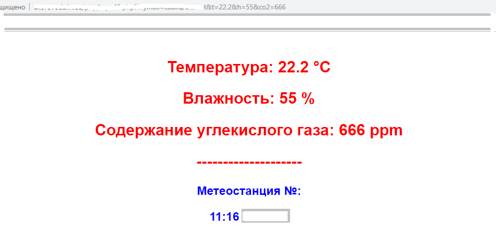
Ahora estamos probando el funcionamiento del sistema de notificación por correo electrónico. Ingrese la línea comentada con la dirección http del código php-script en la barra de direcciones del navegador. Si no se ha olvidado de especificar su correo electrónico en la configuración y en la ventana del navegador (información, como en la imagen a continuación), lo más probable es que no haya problemas para recibir notificaciones. La prueba es especialmente útil cuando transfiero un script php de mi servidor a otro.
Intenciones
En el futuro planeo trabajar en mejorar el termostato (como dicen, ¡no hay límite para la perfección!)
Tareas - mucho:
- Complemente el termostato con un sensor de temperatura con conexión inalámbrica para medir la temperatura exterior.
- Reemplace el par transmisor-receptor de RF con otro par con un rango de comunicación más largo con un voltaje de suministro de no más de 3V. Idealmente, me gustaría armar un analizador alimentado por dos baterías AA durante la temporada de calefacción.
- Evite el formateo manual de la memoria ESP8266 antes de cada cambio en la configuración del termostato al volver a cargar el boceto.
- Extienda el ciclo programable del termostato de diario a semanal.
- Reemplace la pantalla monocromática con color y mayor resolución. Esto permitirá mostrar toda la información sobre el funcionamiento del termostato en un solo cuadro y la salida de los parámetros del aire más allá de los límites establecidos, mediante un cambio de color.
- Luego trate con placas de circuito impreso y una apariencia presentable del termostato.
¿Qué más se puede mejorar? Sugerencias aceptadas, comentarios. Escucho críticas constructivas.
Conclusiones
- Gracias a la conexión a Internet, la funcionalidad del termostato se ha expandido significativamente. Además de la función principal, implementa una serie de otras: desde el envío de alertas por correo electrónico hasta la capacidad de mantener automáticamente la calidad del aire interior.
- Una nueva calidad ha aparecido en el termostato: se puede controlar a través de Internet.
- La facilidad con la que se programa el termostato es agradable: solo tiene que completar el formulario en la página del navegador.
- Ahora puede guardar datos personales en la memoria del termostato, como se hace, por ejemplo, en los enrutadores.
Atencion
El autor no es responsable de un posible negativo al repetir el proyecto. Eres responsable de todo lo que haces.
PD 1. El modelo del proyecto sustituyó dignamente al antiguo termostato, ya que en la cuarta temporada de calefacción ocasionalmente comenzó a "olvidar" encender y apagar el sistema de calefacción.
2. Sobre los enfoques en la solución de algunas de las tareas enumeradas anteriormente, es posible familiarizarse en mis otros artículos sobre Habré:
Mis marcadores sobre un tema de Habr