KDPV "Oh, eso es todo".
Hay pocas posibilidades de que este longrid se convierta en una fuente de sabiduría que da vida a los intelectuales, sofisticado en los secretos de la adivinación en las tarjetas de Carnot y conociendo el significado secreto de la Tercera Forma Normal. Pero si por alguna razón tocaste tu arduino con las manos, un soldador está acumulando polvo en la despensa, entiendes por qué la batería tiene uno más y C ++ tiene dos, entonces los milagros verdaderamente mágicos y sorprendentes no te dejarán indiferente. Por lo tanto, tengo el placer de recomendarles los números de la presentación de hoy del vagabundo circo "Saman with Boxwood" :
- Agregar RAM y ROM a ATtiny13!
- Inteligencia artificial en un microprocesador, pro y contra, o una bella durmiente, bueno, ¿no es una tonta?
- ¿O sigue siendo dura lex sed lex?
- ¿Cómo agregar piernas a ATtiny13?
- Algunas palabras sobre la quinta dimensión: ¿cómo abarrotar lo insoportable?
- Aserrar por la mitad no vírgenes con mezclar el contenido de las mitades (con garantía de recuperación).
- "Alimentando a los Afligidos" (ver el caso anterior de cinco mil personas saturadas con cinco panes de cebada y dos peces).
Si al menos uno de los trucos resulta útil en el futuro para cada vigésimo lector, estaré satisfecho, el artículo fue escrito no en vano.
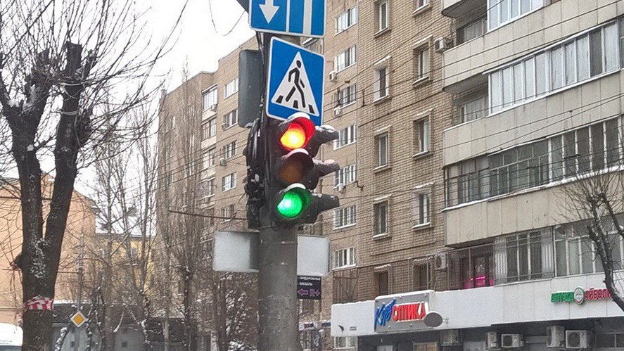
El primer semáforo o Kaa toma la pelea.
La historia comenzó, como en un clásico video prenavideño navideño, cuando la cámara mira a través de una ventana esmerilada en una pequeña y acogedora habitación: un árbol de Navidad en oropel, algodón y juguetes, el olor a mandarina y vino caliente, el cálido escalofrío de las sombras a la luz de las velas. En el gran sofá, Ella endereza la tela escocesa y presiona suavemente su mejilla contra su hombro, escuchando distraídamente a la niña angelical que gesticula con entusiasmo ...
Las personas con experiencia de los padres saben perfectamente bien qué es exactamente lo que pueden escuchar en ese momento. Explicaré a aquellos que aún no han adquirido tal habilidad: con un alto grado de probabilidad, los padres ahora están estupefactos por algo como: “¡Papá! Nosotros mañana! ¡A la guardería! Tengo que! ¡Trae manualidades al concurso de árboles de Navidad! ¡Y quiero el primer lugar!
Es necesario Mañana A nosotros Manualidades Lo mejor
La entrevista relacionada con el cliente muestra los contornos de la declaración de trabajo: necesitamos un semáforo. Y ser hermosa y brillar como una verdadera. Ya en esta etapa, las filas de candidatos para el proyecto ISU se están reduciendo drásticamente: papá no puede corroborar la idea de que un semáforo bonito, suave, cosido de mosaico o tejido de punto sea una representación encarnada de los sueños del Cliente: el semáforo debe estar encendido, ¿qué no está claro?
La noche rodó por el país y el trabajo comenzó a hervir en nuestro país.
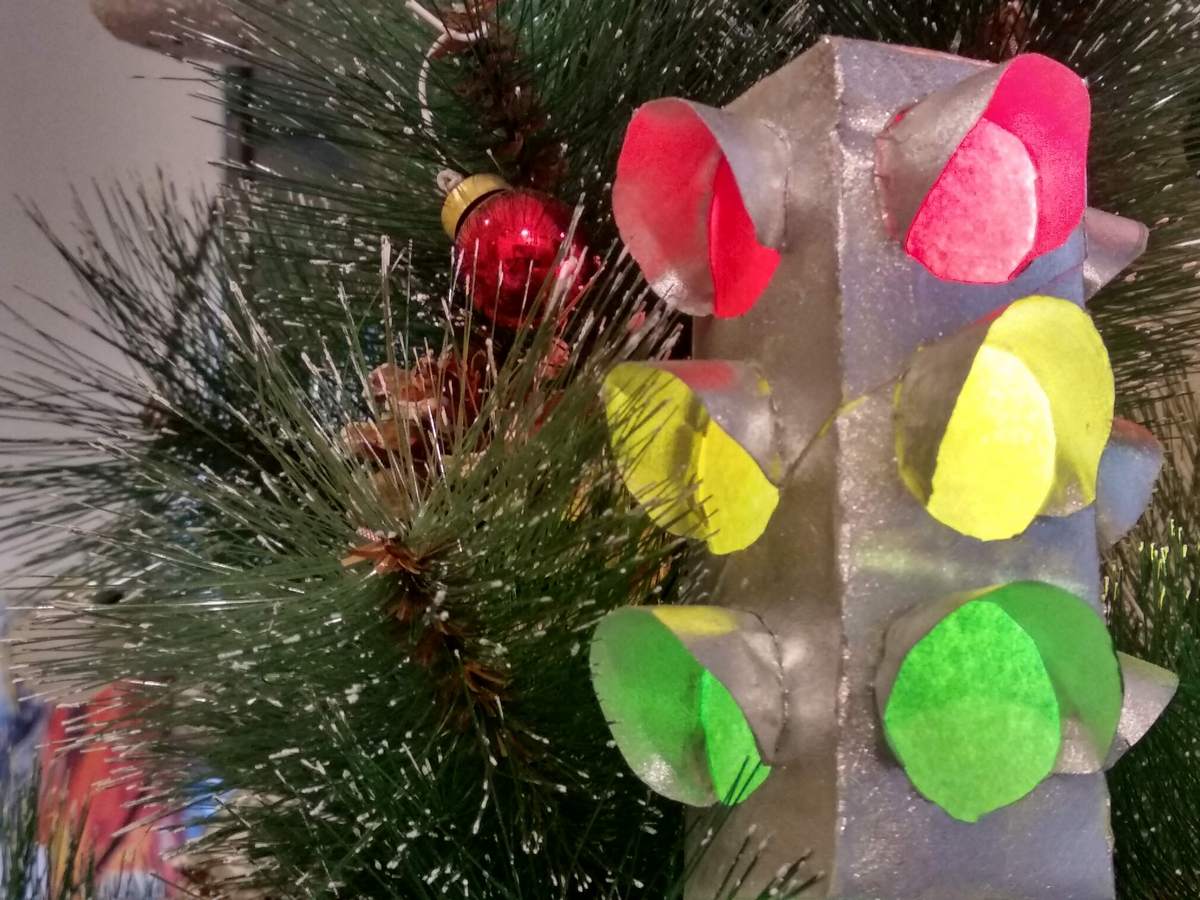
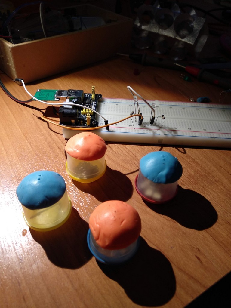
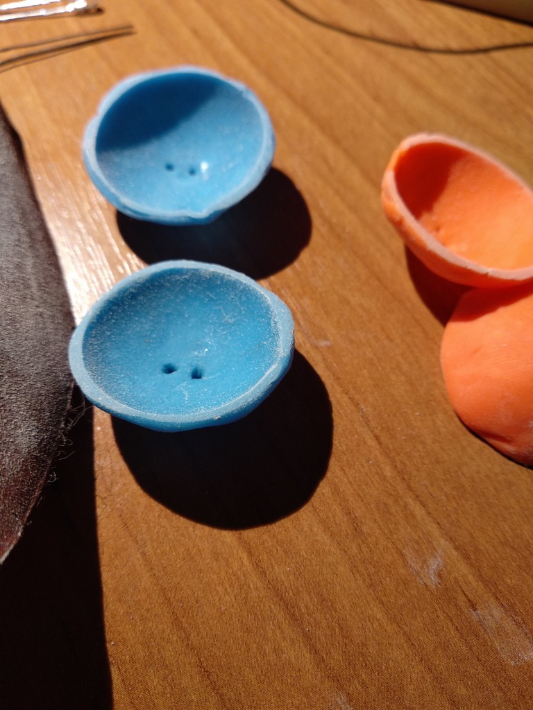
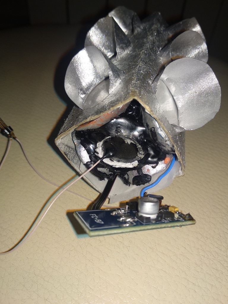
El material del cuerpo del semáforo es una funda de papel higiénico, comprimida para formar una caja. La moneda de diez rublos fue rodeada con un lápiz, y luego se cortaron agujeros con un cuchillo de oficina bajo las luces de la señalización luminosa (el trabajo traumático no es confiable para los niños).
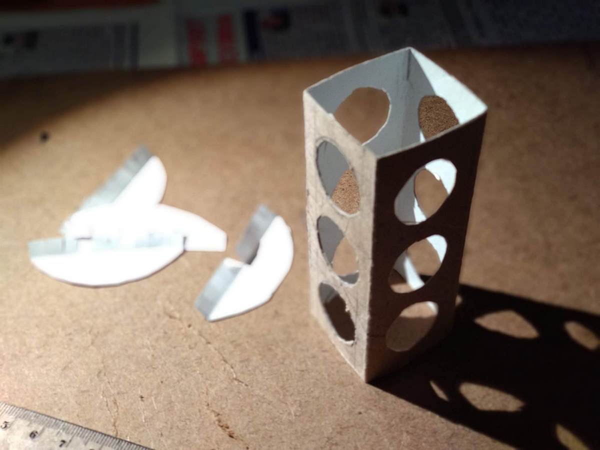
Las cubiertas de la parte superior e inferior del semáforo están cortadas de cartón en su lugar. Los picos sobre las lámparas de acuerdo con el patrón realizado se rodearon en papel de 80 gramos y se cortaron manualmente.

Luego fueron pegados a PVA.
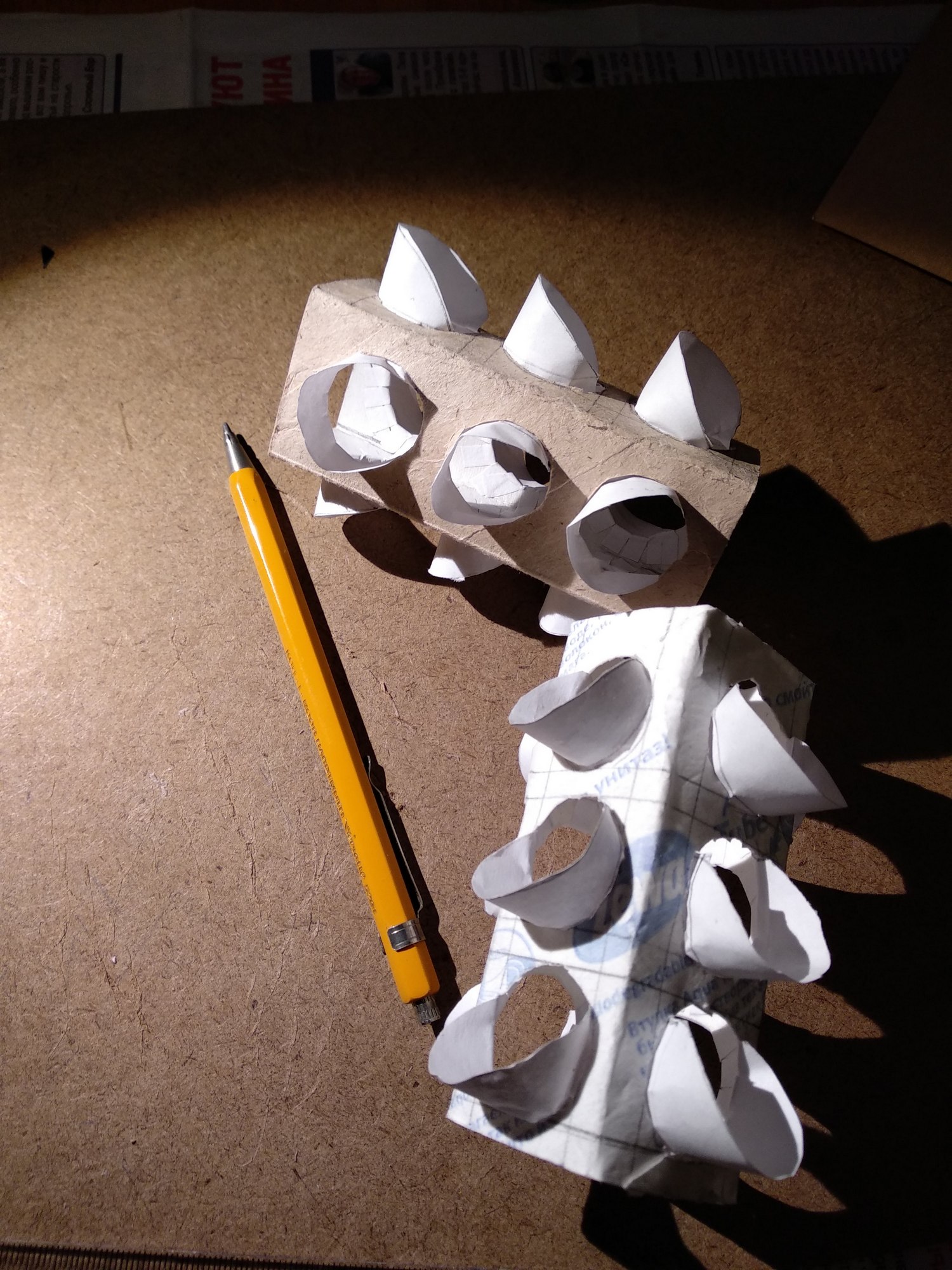
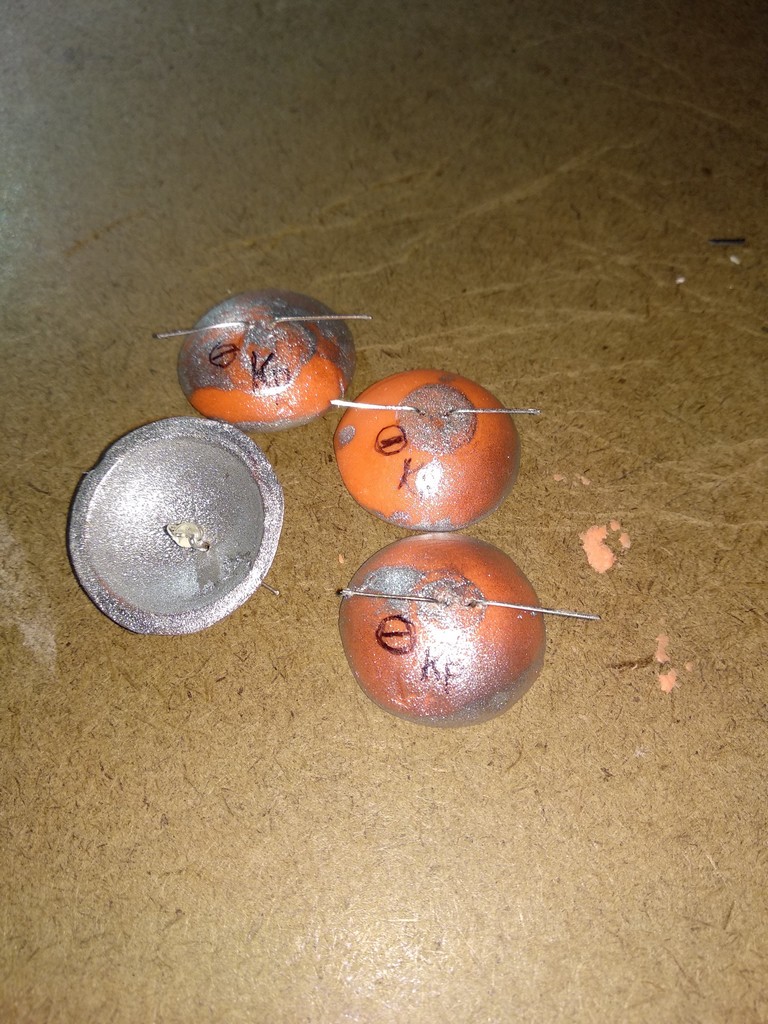
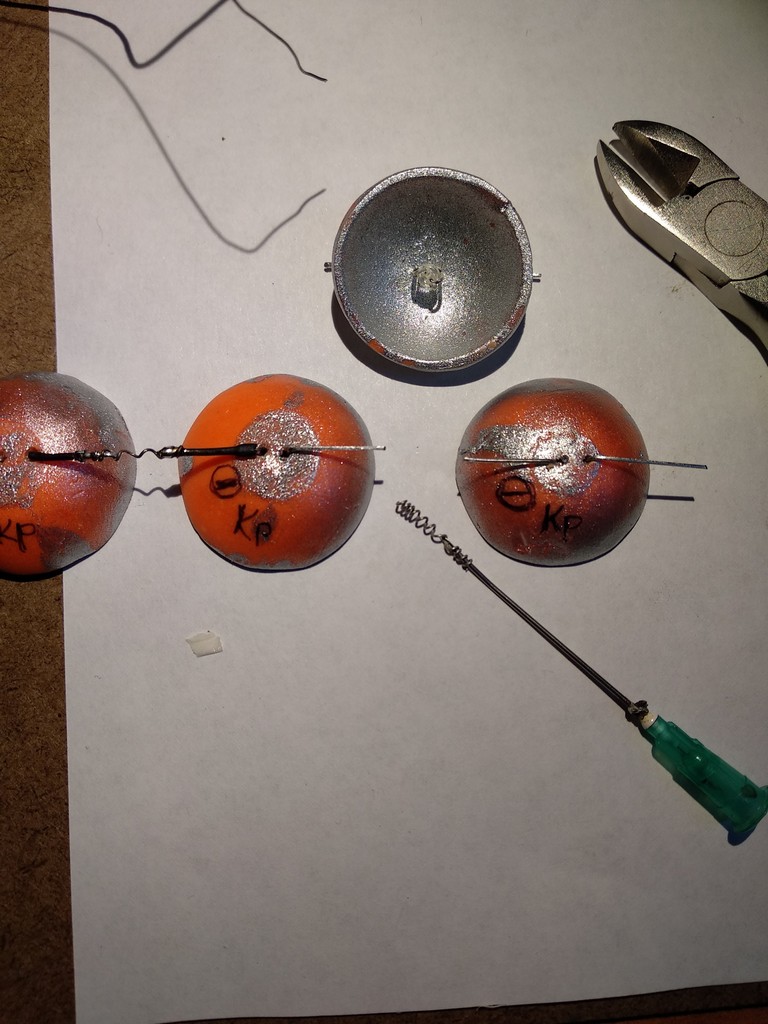
Las estructuras ensambladas fueron arrastradas al patio y pintadas con pinturas acrílicas en aerosol: generosamente plateadas, luego ligeramente negras en la parte superior.
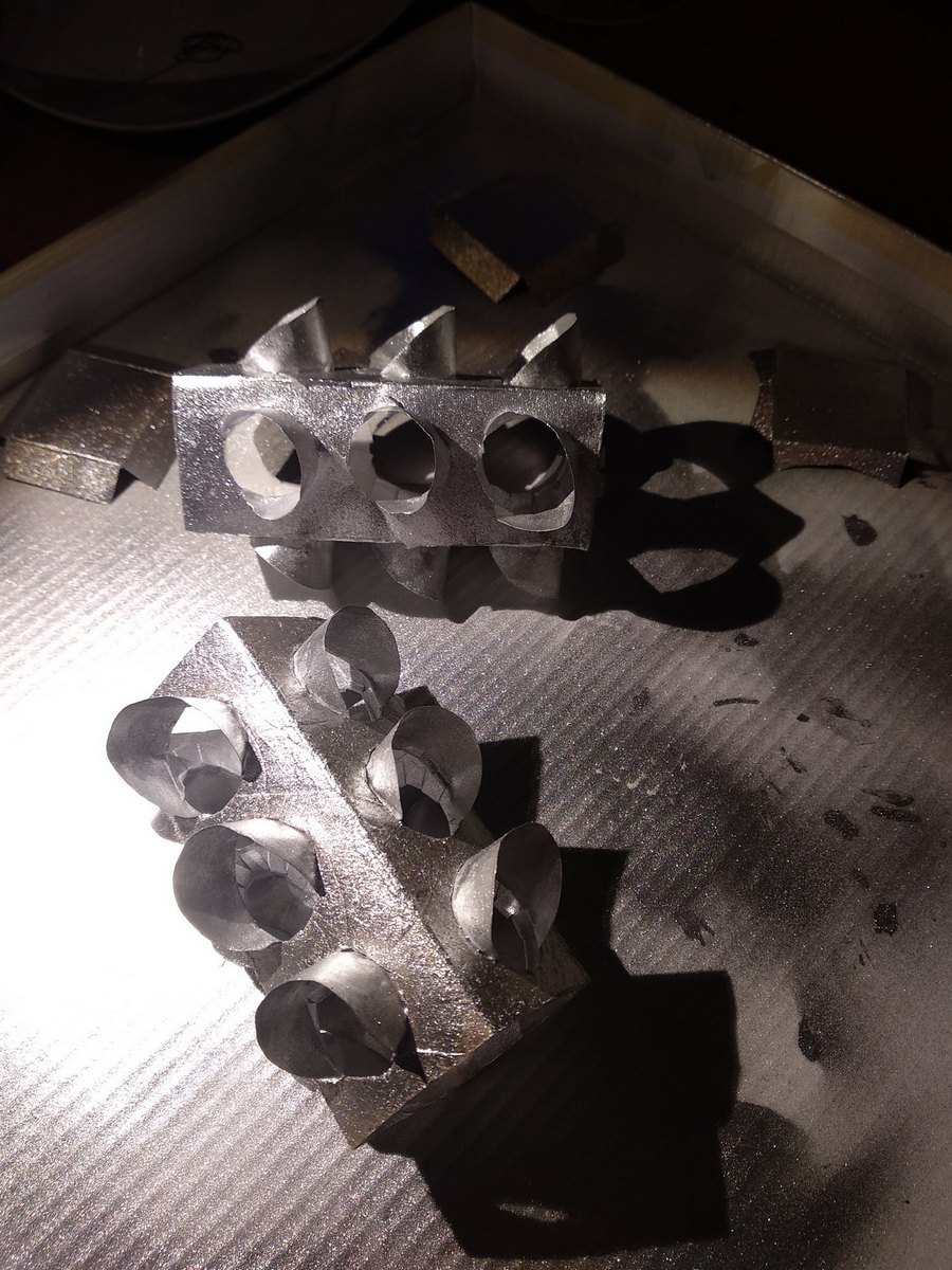
En caso de daños en cualquier etapa, se hicieron tres copias a la vez. Se pegaron tres tiras de papel de color (rojo, amarillo y verde) con filtros de luz dentro del más exitoso.
El resaltado desde el interior fue decidido por un par de LED blancos súper brillantes de los generosos contenedores de la patria (SHZR). El sapo Kaptershchitskaya se negó rotundamente al padre de la presencia de SCHR incluso tres baterías de litio de tableta, y los LED no aceptaron brillar de uno, indicando que eran blancos y brillantes, y la caída de voltaje en ellos fue de 2.8 a 3.9 voltios. Lo máximo que conseguimos negociar con el sapo fue por una batería AA, un anillo de ferrita del acelerador de la placa base quemada y el transistor KT315. Pensando y buscando en Google, papá tuvo que aceptar la oferta. Y teniendo en cuenta la cantidad de bolígrafos juguetones en cada grupo del jardín de infantes, la idea con baterías de litio no parecía particularmente atractiva.
Los cascos de los semáforos en la batería reemplazaron los aromas de las agujas y las mandarinas con un fuerte olor a pintura, mi padre cuidadosamente tocó un soldador en la colofonia, los niños hirieron los transformadores para bloquear los generadores (duplicación de copias), todo salió según el plan ...
Y no, "de repente" esa noche no sucedió: todos los trucos al enrollar un transformador son enrollar inmediatamente el número máximo de vueltas posible con un cable doblado. No confunda el ánodo y el cátodo del LED y los terminales del transistor KT315 y conecte correctamente los extremos de los devanados (o cámbielos si no están iluminados) de acuerdo con el diagrama del circuito. J1: interruptor de encendido de un puente de computadora, que luego se muestra "en el techo" de un semáforo.
Un circuito completamente simple para producir voltaje de CA con picos de 3-7V desde una batería G1 de 1.5V ha sido ampliamente conocido .
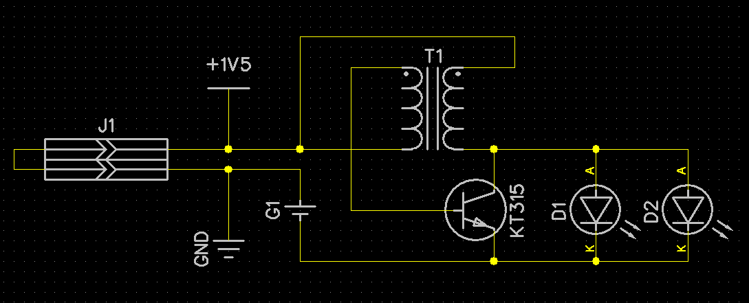
Físicamente, el diagrama del circuito se realiza de la siguiente manera:
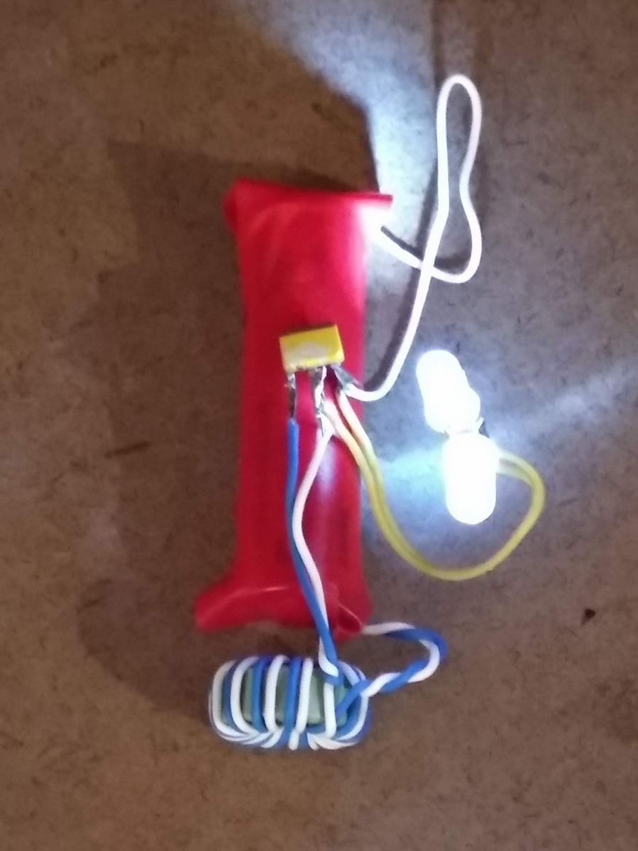
La burocracia tiene una batería alcalina AA.
Y el semáforo en sí es así.
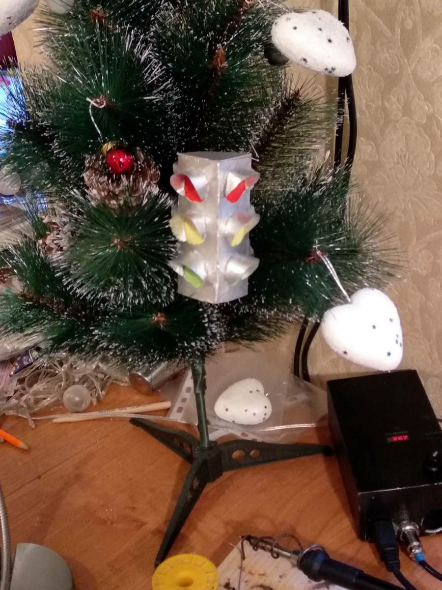
Por la mañana, el niño orgulloso arrastró el producto al jardín de infantes, donde el juguete salpicó y ocupó el centro del escenario en el árbol de Navidad.
Es cierto que no funcionó con el primer lugar en la competencia: la fecha límite para enviar las entradas fue, como resultó, ya hace varios días.
En casa, había dos edificios en el alféizar de la ventana y la insatisfacción con picazón de mi padre con la solución a la tarea "Lo quiero como un semáforo real". Y la idea estaba girando: "¿es posible encajar una solución completa, digamos en el 13 ° lugar, que el sapo ha estado acostado en el ShchZR durante mucho tiempo? ¿Habrá suficientes cinco patas, un kilobyte para el código y 64 bytes de RAM y eso, según lo ordenado, como uno real?"
Así que todo esto fue solo un dicho, un cuento de hadas sobre la solución final del problema del semáforo por delante.
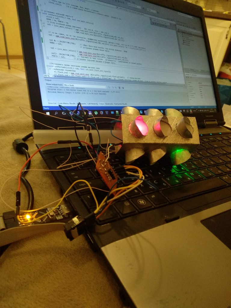
El segundo semáforo, como uno real
Herramientas, materiales y documentación usados.
Lenguaje / marco : C / Arduino 1.6 / 1.8.
IDE : MS Visual Studio 2012 + Visual Micro plugin + git.
CAD : DipTrace.
HW : MK ATtiny13, clon de Arduino Nano en ATmega328, USB-UART en FT232R, programador USBISP de china-noname.
Tecnología PP : LUT .
Herramientas : soldador, pistola de pegamento, horno de cocina, cuchillo, tijeras, cortadores de alambre.
Materiales : de ShchZR : 4 LED de salida rojo, amarillo y verde de la marca noname, condensador de tantalio SMD y un par de resistencias 0805 cada 10k, media docena de resistencias de limitación de corriente 0.25W MF-25, convertidor de CC-CC 5V chino, latas de aerosol con pintura plateada y negra, papel A4, arcilla polimérica de la venta.
Las fuentes y los documentos están disponibles en Github bajo la licencia MIT, las confirmaciones del código fuente coinciden con la iteración del firmware que se describe a continuación, todas las rutas de archivos mencionadas son relativas a la raíz del repositorio.
Documentación :
./docs/ATtiny13A datasheet.pdf [Especificación para MK Atmel ATtiny13A]
./docs/ATmega328 datasheet.pdf [Especificación Atmel ATmega328 MK]
./docs/AVR4027 - Consejos y trucos para optimizar su código C.pdf [Atmel AVR4027: Consejos y trucos para optimizar su código C para microcontroladores AVR de 8 bits]
./docs/AVR4013 - PicoPower basics.pdf [Notas sobre los modos de ahorro de energía]
Desde el IDE de Arduino, como una manta de la nube. Su Wiz es la burla sutil de los jesuitas de todo lo que puede ser sagrado entre los programadores empotrados. Pero Arduino, como ecosistema, vivió, vivirá y vivirá, y debido a la simplicidad de instalar el entorno en computadoras con varios sistemas operativos, y porque fueron los primeros en habilitar, sin ningún gasto especial para un depurador de hardware, utilizando un UART penny y un cargador de arranque patentado, desarrollo en un relleno bastante serio MK. Y aquí está el tío Liao, listo para vender un puñado de clones al precio de un original. El hecho de que en atmegs senior puede depurar la lógica y el funcionamiento del programa, y luego con cambios mínimos para transferir al mismo tinka, esto también es un argumento.
Es normal y cómodo para mí trabajar en MS VisualStudio , no tengo demasiado espacio para AtmelStudio o WinAVR y no quiero encontrarlo, sin un depurador de hardware, no tienen las mejores comodidades. Sobre el complemento VisualMicro, que agrega soporte Arduino a MS VisualStudio , ya ha sido escrito con suficiente detalle y escrito de manera inteligente en Haber.
El enfoque de "Arduino en ATtiny13" en el centro también se consideró hace mucho tiempo y repetidamente .
Brevemente, agregue el módulo MicroCore a la instalación instalada del entorno Arduino, después de lo cual es posible seleccionar el ATtiny13 MK en las tarjetas de destino.
Git: no hay alternativa para ninguno, incluso la mayoría de los proyectos caseros. El hábito es simple, pero correcto: al comenzar a trabajar en cualquier programa, simplemente escriba "git init" en el directorio en la línea de comando. El soporte integrado de MS Visual Studio para confirmaciones en el repositorio local ahorrará tiempo y tiempo más de una vez.
DipTrace, como CAD para circuitos y una placa de circuito impreso, es conveniente, doméstico, el circuito y el cableado son fáciles de usar, es fácil agregar componentes personalizados (UGO, contactos), si lo desea, una placa de circuito impreso con componentes se puede torcer en 3D, se incluye ayuda de alta calidad y lecciones de capacitación. Además, estoy impresionado por su política de licencias: las limitaciones de la licencia estándar sin fines de lucro (1000 pines, 4 capas de señal), gratis para Rusia, Ucrania y la República de Bielorrusia, en el 99% de los casos son suficientes para las artesanías caseras.
No pude lograr que Arduino Nano funcionara correctamente, como un programador pequeño, pero con un programador de ISP USB, el problema se resuelve fácilmente. Esbozar rápidamente archivos por lotes para compilación / firmware - en el directorio ./gcc en el proyecto.
El archivo .ino (pero realmente es C / C ++) se puede compilar correctamente en el estudio "bajo arduino bajo ATtiny13", simplemente se sirve mediante el parámetro de este archivo por lotes en la línea de comandos:
>"./gcc/0_MAKE & upload.cmd" MyArduinoFile.ino
ISP , , .
>"./gcc/0_MAKE & asm.cmd" MyArduinoFile.ino
, , — , AVR . : , .
Upgrade ROM&RAM Arduino ATtiny13
Arduino ( setup(){...}; loop(){...};) "" - int main(){setup(); loop();}, by Arduino.
uint8_t cnt;
void setup() {
    cnt=0;
}
void loop() {
  cnt++;
}
//Program size: 164 bytes (used 16% of a 1 024 byte maximum) (0,57 secs)
//Minimum Memory Usage: 5 bytes (8% of a 64 byte maximum)
, :
uint8_t cnt;
int main(){
    cnt=0;      // < setup()
    while(1){
        cnt++;  // < loop()
    }
}
//Program size: 60 bytes (used 6% of a 1 024 byte maximum) (1,23 secs)
//Minimum Memory Usage: 1 bytes (2% of a 64 byte maximum)
16% 6% , , 6% . , — 64 .
, , : . , , , , . , , , . , : CPU , . — , N . ""-CPU , (9.6 / 1024 = 9370 , ) 1/9370 = 0.0001067 . 8- . , , , " ". , , , "". 37 (256 0.0001067 = 0.027315; 0.027315 37 = 1.01065 ~= 1s).
: - (HW , 1024 ), 8 — , , .
: globalTimer volatile, , , , CPU , .
#include <avr/io.h>         //     IDE -
#include <avr/sleep.h>      // ,
#include <avr/interrupt.h>          //
volatile uint16_t  globalTimer;     //     64
//  -    globalTimer  1/37
ISR(TIM0_OVF_vect){
    globalTimer++;  //       . , ,  while(1)   .
}
int main() {
    //     "  -".
    set_sleep_mode(SLEEP_MODE_IDLE);    //   - .
    sleep_enable();                 //
    TCCR0B = _BV(CS02) | _BV(CS00); //  0 - clock frequency / 1024
    TIMSK0 |= _BV(TOIE0);           //      overflow interrupt
    sei();                          //
    while(1){
        //.........
        sleep_cpu();    //     -   .
    }
}
//Program size: 128 bytes (used 13% of a 1 024 byte maximum) (0,86 secs)
//Minimum Memory Usage: 2 bytes (3% of a 64 byte maximum)
" 4 : , , "()
, , .
, , CPU, / / . GPIO.
Arduino : Arduino pin_number ( ):
pinMode(pin_number, OUTPUT); // INPUT -
/ , — .
Value = digitalRead(pin_input_number);  //Value -  HIGH  LOW (1  0)
digitalWrite(pin_outpit_number, Value);       //   pin_outpit_number - HIGH  LOW
"" , Wiring , , Arduino ( ) ( ) ( ) ( ).
.. Arduino 7 11 PD7 — D.
digitalRead, digitalWrite, pinMode .., , , , Wiring- , .
— , . , DIHALT .
- (GPIO) , 8- — 8 . , 6 (. ATtiny13 pinout, ), PB0 PB5, PB5 — MK . - : ( "B") DDRB, PINB PORTB. — , , . PB0, PB1, PB2, PB3, PB4, PB5 — B. #include <avr/io.h> ( iotn13.h ), (PB0 0,..., PB5 — 5) IDE, Arduino.
: , , . , - , , , DDRx GPIO , — . PORTx — , "- ", , — , PINx. , 50 0 1. , .
,PB2 HIGH, +5, PB3 LOW, 0, PB0 , — .
DDRB , PB0, ( ) = 0 (PB0 ), = 1 (PB2, PB3 — ), .. 110, — , 1 0 — .
DDRB = 12;  //  000001100    - 12
//        (!)
//        pinMode().
— PORTB , =1 (PB2 HIGH), — (PB3 LOW), — , 01
PORTB = 8;  //(dec)8 === (bin)000001000
//  -        .
PINB, , — .
, — .
3 (PB3) : 1 , 3 .
3<<00000001 === PB3<<1 // — 00001000
, _BV(x), (x<<1), .. _BV(PB3) — 1.
_BV(PB3) | _BV(PB2) 00001100 (| — ).
: , , .
PORTB |= _BV(PB3) | _BV(PB2); // 2 3 == 1, PB2 PB3 HIGH, PORTB
0 , , . 0 1 . , , 1 , 0 — 0 .
PORTB &= ~(_BV(PB3) | _BV(PB2)); // PORTB 2 3 - , LOW, .
HW , - 0, Timer0. GPIO, , , datasheet ATtiny13, - -, Ilya Ananev - 0 ATmega328.
, , .
TCCR0B = _BV(CS02) | _BV(CS00);    //    CS02  CS00  1 -   0 = clock frequency / 1024
TIMSK0 |= _BV(TOIE0);           //   TOIE0  1 -     TIM0_OVF
//      TIMSK0 = _BV(TOIE0);
.
, . , , . - , , , (!) .
, . " 27.02.13" 7 52289-2004 , .
( ): , , , , , .
"* " " 2 , — 3 .
3 1 /.*"
, ( , / — PERIOD_0 PERIOD_4, — ).
#define ONE_SECOND  37      //     1
#define QT_SECOND   9       //

#define PERIOD_FLASH_GREEN  QT_SECOND           //    ( ) -
#define PERIOD_FLASH_YELLOW ONE_SECOND * 1      //    -    -
                                                        //  ---
#define PERIOD_0    ONE_SECOND * 10 //R G R G   0.  ---   (10 )
#define PERIOD_1    ONE_SECOND * 3  //R g R g   1.  ---   (3 )
#define PERIOD_2    ONE_SECOND * 1  //R Y R Y   2.  ---  (1 )
#define PERIOD_3    ONE_SECOND * 2  //RY Y RY Y 3. + ---  (2 )
#define PERIOD_4    ONE_SECOND * 7  //G R G R   4.  ---   (7 )
#define PERIOD_5    ONE_SECOND * 3  //g R g R   5.   --- (3 )
#define PERIOD_6    ONE_SECOND * 1  //Y R Y R   6.  ---  (1 )
#define PERIOD_7    ONE_SECOND * 2  //Y RY Y RY 7.  --- + (2 )
, , .
typedef struct{
    const uint8_t ddr_val_0;    // DDRB value -
    const uint8_t port_val_0;   // PORTB value   -
    const uint8_t ddr_val_1;    // DDRB value  -   "",
    const uint8_t port_val_1;   // PORTB value -
    const uint16_t flash_period;    // period of flashing -   _val_1  _val_0
    const uint16_t signal_period;   // period of this lighting state
}lightSignalization;            //   , _0  _1 -   , flash_long -
// flash_period == 0,   ,   _val_0.
// signal_period == 0,         .
, 128 — , .
ATtiny13 ( ?) -
, , - - , : 6 . - denvo " ? RESET" 5- , , , , - .
- : --, .. , 7 .
— , , , 8, ?
, -, "reset", PB5, .
, ? , , , . , , , , , .
, , 8 9 - , 8 — . , -, , , , .
— .
: — . .
:
1 PORTB |= _BV(GREEN_PIN) — ( ) , 0 .. PORTB &= ~(_BV(GREEN_PIN)) — ( ).
, , ?
(DDRB |= _BV(GREEN_PIN)) , DDRB &= ~(_BV(GREEN_PIN)), GREEN_PIN Hi-Z . (2.2 * 4) 5, .
.
— .. , , .
, ,, . , — , 37/2=18 , , . :
) , , , , ;
) — , " " 4 ;
) , 4 ( PERIOD_2->PERIOD_3 PERIOD_6->PERIOD_7);
) 4 .
.
// PINB === 0 0 0 g r y0 btt y1
#define RED_PIN     PB3     // OUT: 1 - "-" , 0 - "-" , IN -  , ,  (!)
#define YELLOW0_PIN PB2     // OUT: 1 -  "-"
#define YELLOW1_PIN PB0     // OUT: 1 -  "-"
#define GREEN_PIN   PB4     // OUT: 1 - "-" , 0 - "-" , IN -  , ,  (!)

#define RED     _BV(RED_PIN)        // _BV -     (), 1<<VALUE
#define YELL0   _BV(YELLOW0_PIN)        //    -
#define YELL1   _BV(YELLOW1_PIN)
#define GREEN   _BV(GREEN_PIN)      //    - (  0 -   -)  DDRB.GreenPin=1
— . , , — , .
#define BUTTON_PIN      PB1
#define BUTTON_ON  !(PINB & _BV(BUTTON_PIN))    //( (PINB & _BV(BUTTON_PIN)) == 0)  //  " " -   LOW
#define BUTTON_OFF (PINB & _BV(BUTTON_PIN))     //  " " -    HIGH, (     )
, , n ( ) n(n−1) = n²−n . 4 12 , . « , » « , » .
*** — , DDRx|PORTx, , .. . — , , .
.***
: ?
lightSignalization. lightSignalization . 0 7 , 8 — , 9 — , "" . , 0 7, . , , . 3 ( 0 7) 8 -- . if- , . , .
lightSignalization traffic_signals[] = {//
 // {DDRB0, PORTB0,   DDRB_when_flashingif, PORTB_when_flasingif (if flashing),   continous of half-period flashing,   continous curr mode runing}
    {RED|GREEN, RED,   0, 0,   0, PERIOD_0},                    // R G R G
    {RED, RED,  RED|GREEN, RED,   QT_SECOND, PERIOD_1},     // R g R g - flash east green
    {RED|YELL1, RED|YELL1,   0, 0,   0, PERIOD_2 },         // R Y1 R Y1
    {RED|YELL0|YELL1, RED|YELL0|YELL1,  0, 0,   0, PERIOD_3 },  // RY0 Y1 RY0 Y1
    {RED|GREEN, GREEN,   0, 0,   0, PERIOD_4},              // G R G R
    {RED|GREEN, GREEN,   RED, 0,    QT_SECOND, PERIOD_5 },  // g R g R - flash nord green
    {RED|YELL0, YELL0,   0, 0,   0, PERIOD_6},                  // Y0 R Y0 R
    {RED|YELL0|YELL1,  YELL0|YELL1,   0, 0,   0, PERIOD_7  },       // Y0 RY1 Y0 RY1

    {YELL0|YELL1, YELL0|YELL1,   YELL0|YELL1, 0,  ONE_SECOND, 0},   // y0 y1 y0 y1 - flash yellows lights
    {0, 0,   0, 0,   0, 0}          // traffic lights off, DDR in, Hi-Z
};

//       lightSignalization traffic_signals[]
#define LIGHT_NUM_YELLOW_FLASH  8       //       -  - flash yellows lights
#define LIGHT_NUM_STD_START     0       //
#define LIGHT_NUM_LIGHTS_OFF    9       //      -   - traffic lights off
lightSignalization 8 . .. traffic_signals[] 10 80 (, 64 , 2 ). , .
, , , — ROM, , RAM , .
-
const lightSignalization traffic_signals[] PROGMEM= {...
,
<avr/pgmspace.h> pgm_read_byte_near() pgm_read_word_near()
char shortint .
3 .
, .
traffic_signals[] — LIGHT_NUM_LIGHTS_OFF
{0, 0, 0, 0, 0, 0} // traffic lights off
— lightSignalization , — , lightSignalization.signal_period==0 (.. ), lightSignalization.flash_period==0, .. .
, .
traffic_signals[] — LIGHT_NUM_YELLOW_FLASH
{YELL0|YELL1, YELL0|YELL1, YELL0|YELL1, 0, ONE_SECOND, 0}, // y0 y1 y0 y1 — flash yellows lights
: lightSignalization.signal_period==0. lightSignalization.flash_period=ONE_SECOND, :
DDRB = YELL0|YELL1;     // YELL0, YELL1 -
PORTB = YELL0|YELL1;    // YELL0, YELL1 = HIGH -
DDRB = YELL0|YELL1;     // // YELL0, YELL1 -
PORTB = 0;              // YELL0, YELL1 = LOW -
, --.
, .
traffic_signals[] — LIGHT_NUM_STD_START
{RED|GREEN, RED, 0, 0, 0, PERIOD_0}, // R G R G
: lightSignalization.flash_period==0.
DDRB = RED|GREEN; //RED GREEN — , .
PORTB = RED; // RED — HIGH (- )
// GREEN — LOW ( , - — )
lightSignalization.signal_period==PERIOD_0, .
current_signal. 2 — , lightSignalization.
uint8_t current_signal;     // 1    ,   traffic_signals
uint16_t tl_flash_end;      // 2       ( !0),
uint16_t tl_signal_end;     // 2            ( !0)
tl_signal_end != 0, globalTimer>tl_signal_end current_signal. 0 current_signal, 3, .
current_signal = current_signal & B00000111;
current_signal &= LIGHT_NUM_STD_MASK ; //current_signal & B00000111;
current_signal , 0 7.
globalTimer — .
#include <limits.h>         // USHRT_MAX
#include <avr/sleep.h>      // ,
#include <avr/interrupt.h>  //
#include <avr/pgmspace.h>   //

#define ONE_SECOND  37      //     1
#define QT_SECOND   9       //
#define MAX_GLOBAL_TIMER_VALUE  (USHRT_MAX / 2)     // uint16_t globalTimer -   . 65535 /2
//     ,  MAX_GLOBAL_TIMER_VALUE - 1
#define PERIOD_FLASH_GREEN  QT_SECOND           //    ( ) -
#define PERIOD_FLASH_YELLOW ONE_SECOND * 1      //    -    -
                                                        //  ---
#define PERIOD_0        ONE_SECOND * 10     //R G R G   0.  ---   (15 )
#define PERIOD_1        ONE_SECOND * 3      //R g R g   1.  ---   (3 )
#define PERIOD_2        ONE_SECOND * 1      //R Y R Y   2.  ---  (1 )
#define PERIOD_3        ONE_SECOND * 2      //RY Y RY Y 3. + ---  (2 )
#define PERIOD_4        ONE_SECOND * 7      //G R G R   4.  ---   (10 )
#define PERIOD_5        ONE_SECOND * 3      //g R g R   5.   --- (3 )
#define PERIOD_6        ONE_SECOND * 1      //Y R Y R   6.  ---  (1 )
#define PERIOD_7        ONE_SECOND * 2      //Y RY Y RY 7.  --- + (2 )

typedef struct{
    const uint8_t ddr_val_0;    // DDRB value
    const uint8_t port_val_0;   // PORTB value
    const uint8_t ddr_val_1;    // DDRB value
    const uint8_t port_val_1;   // PORTB value
    const uint16_t flash_period;    // period of flashing -   _val_1  _val_0
    const uint16_t signal_period;   // period of this lighting state
}lightSignalization;            //   , _0  _1 -   , flash_long -

//    (PINS === 0 0 0 g r y0 btt y1):
 //     ""
#define BUTTON      PB1
#define RED_PIN     PB3     // OUT: 1 - "-" , 0 - "-" , IN -  , ,  (!)
#define YELLOW0_PIN PB2     // OUT: 1 -  "-"
#define YELLOW1_PIN PB0     // OUT: 1 -  "-"
#define GREEN_PIN   PB4     // OUT: 1 - "-" , 0 - "-" , IN -  , ,  (!)

#define BUTTON_ON  !(PINB & _BV(BUTTON))    //( (PINB & _BV(BUTTON)) == 0)  //  " "
#define BUTTON_OFF  (PINB & _BV(BUTTON))    // ~(PINB & _BV(BUTTON)) -\\- " "

#define RED     _BV(RED_PIN)            // _BV -     (), 1<<VALUE
#define YELL0   _BV(YELLOW0_PIN)        //
#define YELL1   _BV(YELLOW1_PIN)
#define GREEN   _BV(GREEN_PIN)

//       lightSignalization traffic_signals[]
#define LIGHT_NUM_YELLOW_FLASH  8       //       -  - flash yellows lights
#define LIGHT_NUM_STD_START     0       //
#define LIGHT_NUM_LIGHTS_OFF    9       //      -   - traffic lights off
#define LIGHT_NUM_STD_MASK      7       // ___++ &LIGHT_NUM_STD_MASK -    0  7

//....................................
//
const lightSignalization traffic_signals[] PROGMEM= {   //   ,  ,   -, PINS === 0 0 0 g r y0 btt y1
 // {DDRB0, PORTB0,   DDRB_flashing, PORTB_flasinf (if flashing),   continuous of half-period flashing,   continuous id mode running}
    {RED|GREEN, RED,   0, 0,   0, PERIOD_0},                    // R G R G
    {RED, RED,  RED|GREEN, RED,   QT_SECOND, PERIOD_1},     // R g R g - flash east green
    {RED|YELL1, RED|YELL1,   0, 0,   0, PERIOD_2 },             // R Y1 R Y1
    {RED|YELL0|YELL1, RED|YELL0|YELL1,  0, 0,   0, PERIOD_3 },  // RY0 Y1 RY0 Y1
    {RED|GREEN, GREEN,   0, 0,   0, PERIOD_4},                  // G R G R
    {RED|GREEN, GREEN,   RED, 0,    QT_SECOND, PERIOD_5 },      // g R g R - flash nord green
    {RED|YELL0, YELL0,   0, 0,   0, PERIOD_6},                  // Y0 R Y0 R
    {RED|YELL0|YELL1,  YELL0|YELL1,   0, 0,   0, PERIOD_7  },   // Y0 RY1 Y0 RY1

    {YELL0|YELL1, YELL0|YELL1,   YELL0|YELL1, 0,  ONE_SECOND, 0},   // y0 y1 y0 y1 - flash yellows lights
    {0, 0,   0, 0,   0, 0}              //  traffic lights off,
};

volatile uint16_t  globalTimer;     //     64
uint8_t current_signal;     // 1    ,   traffic_signals
uint16_t tl_flash_end;      // 2       ( !0),
uint16_t tl_signal_end;     // 2            ( !0)

//....................................
void setPeriods(uint8_t num, bool set_both_flash_and_signal);   //  tl_flash_end, tl_signal_end
void setPorts(uint8_t num, bool use_main_values);               //

//....................................
//
//  -    globalTimer  1/37
ISR(TIM0_OVF_vect){
    globalTimer++;  //       . ,   while(1)   .
}

int main() {
//
bool use_main_values = true;            // lightSignalization._val_0 (1)  lightSignalization._val_1 (0)? -
current_signal = LIGHT_NUM_STD_START;   //   .     .

    //     "  -".
    set_sleep_mode(SLEEP_MODE_IDLE);    //   - .
    sleep_enable();                 //

    TCCR0B = _BV(CS02) | _BV(CS00); //  0 - clock frequency / 1024
    TIMSK0 |= _BV(TOIE0);           //      overflow interrupt

    sei();      //
    while(1){
        //   ?
        if(globalTimer > MAX_GLOBAL_TIMER_VALUE){
            globalTimer -= MAX_GLOBAL_TIMER_VALUE;          //
            //
            if(tl_flash_end){
                tl_flash_end -= MAX_GLOBAL_TIMER_VALUE;     //   ,
            }
            if(tl_signal_end){
                tl_signal_end -= MAX_GLOBAL_TIMER_VALUE;    // //   ,
            }
            // setPeriods(currentMode, false); //   12  ,  tl_.._end   ,
        }

                //      (tl_flash_end !=0 )
        if(tl_flash_end){
            //
            if(globalTimer > tl_flash_end){
                use_main_values = !use_main_values;             // !use_main_values -      ))
                setPorts(current_signal, use_main_values);      //
                setPeriods(current_signal, false);              //     ,
            }
        }

        //         -    operating_std     - --
        if(tl_signal_end){
            //       (use_main_values -       -  )
            if((globalTimer > tl_signal_end)  && use_main_values){
                current_signal ++;                          //
                current_signal &= LIGHT_NUM_STD_MASK;       //    3-,        0  7
                use_main_values = true;                     //  -
                setPorts(current_signal, use_main_values);  //
                setPeriods(current_signal, true);           //
            }
        }

        sleep_cpu();    //      -   .
    }
}

    //
 void setPorts(uint8_t num, bool use_main_values){
    uint8_t val;
    DDRB = 0; PORTB = 0;
    //    () - ddr_val_0, else = ddr_val_1
//  val = (use_main_values) ? pgm_read_byte_near(&(traffic_signals[num].ddr_val_0))
//                          : pgm_read_byte_near(&(traffic_signals[num].ddr_val_1));

    //   ,  , ,  ,   ,   14 (!!!)   .
    val = pgm_read_byte_near(&(traffic_signals[num].ddr_val_0)+( (use_main_values) ? 0 : 2) );
    val &= ~_BV(BUTTON);    //     -
    DDRB = val;             //

    val = (use_main_values) ? pgm_read_byte_near(&(traffic_signals[num].port_val_0))
                            : pgm_read_byte_near(&(traffic_signals[num].port_val_1));
    val|= _BV(BUTTON);  //     -  -
    PORTB = val;        //
}

 //     (
void setPeriods(uint8_t num, bool set_both_flash_and_signal){
//
    tl_flash_end = pgm_read_word_near (&(traffic_signals[num].flash_period));   //
    tl_flash_end = (tl_flash_end)? tl_flash_end + globalTimer : 0;  //    -
    //if(tl_flash_end){         tl_flash_end += globalTimer;    } <-     8

    //     -
    if(set_both_flash_and_signal){
        tl_signal_end = pgm_read_word_near(&(traffic_signals[num].signal_period));
        tl_signal_end = (tl_signal_end)? tl_signal_end + globalTimer : 0;           //     ,
    }
}

//Program size: 610 bytes (used 60% of a 1 024 byte maximum) (0,58 secs)
//Minimum Memory Usage: 7 bytes (11% of a 64 byte maximum)
, . — btn_cnt ( ), ( ) .
#define PERIOD_PRESS_BUTTON_SHORT   QT_SECOND           //      -
#define PERIOD_PRESS_BUTTON_LONG    QT_SECOND*6         //      - /
uint8_t scan_button_cnt;    //
        //
        if(BUTTON_ON){
            if(scan_button_cnt<USHRT_MAX){
                scan_button_cnt++;      //   1/37
            }
            if(scan_button_cnt > PERIOD_PRESS_BUTTON_SHORT){
                    // ,
            }
            if(scan_button_cnt > PERIOD_PRESS_BUTTON_LONG){
                    //
            }
        }
— .

SLEEP_MODE_IDLE ( CPU), PwrDown SLEEP_MODE_PWR_DOWN —
. 7.Power management and sleep modes ATtiny13 , 5-10 , .
8- , — 2 .
//  uint8_t f_button_state_flags;       //

//      MODES:  wakeup 11 -> work 00 -> tosleep 01 -> pwrdown 11 -> wakeup 11
#define MODE_LBIT 0
#define MODE_HBIT 1
#define FORCE_SET_NEW_SIGNAL_BIT        2   //             current_signal
//    3
#define LIGHT_SIGNAL_ALT_MODE_BIT       4   // =0 (--)  =1 ( )
#define USE_FIRST_VALUES_LIGHT_BIT      5   //     -  lightSignalization
#define SHORT_PRESS_FLAG_BIT    6   // , 1
#define LONG_PRESS_FLAG_BIT     7 // , 1
, — , — CPU . , if-.
#include <limits.h>         // USHRT_MAX
#include <avr/io.h>         //     IDE
#include <avr/sleep.h>      // ,
#include <avr/interrupt.h>  //
#include <avr/pgmspace.h>   //

#ifdef GIMSK    //  ATtiny13 -
#define F_CPU 9600000UL     //      ,
#define ONE_SECOND  37      //     1
#define QT_SECOND   9       //
// GIMSK &= ~_BV(INT0); -   INT0
#define DISABLE_EXTERNAL_INT0   GIMSK &= ~(_BV(INT0)); GIFR  &= ~(_BV(INTF0))   //EIMSK/EIFR
//GIMSK |= _BV(INT0) -   INT0
#define ENABLE_EXTERNAL_INT0    GIMSK |= _BV(INT0)  ; GIFR  &= ~(_BV(INTF0))
#else           // 328 -
#define F_CPU 16000000UL
#define ONE_SECOND  64      //     1  - .
#define QT_SECOND   16      //
// 328 INT0 -  PD2...     ,       (,  ),
#define DISABLE_EXTERNAL_INT0   EIMSK &= ~(_BV(INT0)); EIFR  &= ~(_BV(INTF0))
// ,   -  EICRA - ISC00-ISC01 == 00, lo level, EIMSK - INT0, EIFR-INTF0
#define ENABLE_EXTERNAL_INT0    EIMSK |= _BV(INT0)  ; EIFR  &= ~(_BV(INTF0))
#endif

#define MAX_GLOBAL_TIMER_VALUE  (USHRT_MAX / 2)     // uint16_t globalTimer -   . 65535 /2
//     ,  MAX_GLOBAL_TIMER_VALUE - 1
#define PERIOD_PRESS_BUTTON_SHORT   QT_SECOND/2         //      ( - ) -
#define PERIOD_PRESS_BUTTON_LONG    QT_SECOND*4         //      - /
#define PERIOD_FLASH_GREEN          QT_SECOND           //     ( ) -
#define PERIOD_FLASH_YELLOW         ONE_SECOND * 1      //     -    -

                                            //  ---
#define PERIOD_0        ONE_SECOND * 5      // R G R G  0.  ---   (5 )
#define PERIOD_1        ONE_SECOND * 3      //R g R g   1.  ---   (3 )
#define PERIOD_2        ONE_SECOND * 1      //R Y R Y   2.  ---  (1 )
#define PERIOD_3        ONE_SECOND * 2      //RY Y RY Y 3. + ---  (2 )
#define PERIOD_4        ONE_SECOND * 7      // G R G R  4.  ---   (7 )
#define PERIOD_5        ONE_SECOND * 3      //g R g R   5.   --- (3 )
#define PERIOD_6        ONE_SECOND * 1      //Y R Y R   6.  ---  (1 )
#define PERIOD_7        ONE_SECOND * 2      //Y RY Y RY 7.  --- + (2 )

//  /  .     -
typedef struct{
    const uint8_t ddr_val_0;    // DDRB value
    const uint8_t port_val_0;   // PORTB value
    const uint8_t ddr_val_1;    // DDRB value
    const uint8_t port_val_1;   // PORTB value
    const uint16_t flash_period;    // period of flashing -   _val_1  _val_0 ( =0,  )
    const uint16_t signal_period;   // period of this lighting state ( =0,       )
}lightSignalization;            //   , _0  _1 -   , flash_long -

//    (PINS === 0 0 0 g r y0 btt y1):
 //     ""
#define BUTTON_PIN  PB1     // ,   INT0. ,   ,  = LOW
#define RED_PIN     PB3     // OUT: 1 - "-" , 0 - "-" , IN -  , ,  (!)
#define YELLOW0_PIN PB2     // OUT: 1 -  "-"
#define YELLOW1_PIN PB0     // OUT: 1 -  "-"
#define GREEN_PIN   PB4     // OUT: 1 - "-" , 0 - "-" , IN -  , ,  (!)

#define BUTTON_ON  !(PINB & _BV(BUTTON_PIN))    //( (PINB & _BV(BUTTON)) == 0)  //  " "
#define BUTTON_OFF  (PINB & _BV(BUTTON_PIN))    // ~(PINB & _BV(BUTTON)) -\\- " "

#define RED     _BV(RED_PIN)            // _BV -     (), 1<<VALUE
#define YELL0   _BV(YELLOW0_PIN)        //    -
#define YELL1   _BV(YELLOW1_PIN)
#define GREEN   _BV(GREEN_PIN)          //    - (  0 -   -)  DDR=1

//      lightSignalization traffic_signals[]
#define LIGHT_NUM_YELLOW_FLASH  8       //       ( ) -  - flash yellows lights
#define LIGHT_NUM_STD_START     0       //        (--)
#define LIGHT_NUM_LIGHTS_OFF    9       //      -   - traffic lights off
#define LIGHT_NUM_START_SHOW    10      //
#define LIGHT_NUM_ERR           11      //   -

#define MASK_LIGHT_NUM_STD      7       // ___++ &= LIGHT_NUM_STD_MASK -    0  7

//....................................
//
const lightSignalization traffic_signals[] PROGMEM= {   //   ,  ,   -, PINS === 0 0 0 g r y0 btt y1
 // {DDRB0, PORTB0,   DDRB_flashing, PORTB_flasinf (if flashing),   continuous of half-period flashing,   continuous id mode running}
    {RED|GREEN, RED,   0, 0,   0, PERIOD_0},                    // R G R G
    {RED, RED,  RED|GREEN, RED,   QT_SECOND, PERIOD_1},         // R g R g - flash east green
    {RED|YELL1, RED|YELL1,   0, 0,   0, PERIOD_2 },             // R Y1 R Y1
    {RED|YELL0|YELL1, RED|YELL0|YELL1,  0, 0,   0, PERIOD_3 },  // RY0 Y1 RY0 Y1
    {RED|GREEN, GREEN,   0, 0,   0, PERIOD_4},                  // G R G R
    {RED|GREEN, GREEN,   RED, 0,    QT_SECOND, PERIOD_5 },      // g R g R - flash nord green
    {RED|YELL0, YELL0,   0, 0,   0, PERIOD_6},                  // Y0 R Y0 R
    {RED|YELL0|YELL1,  YELL0|YELL1,   0, 0,   0, PERIOD_7  },   // Y0 RY1 Y0 RY1

    {YELL0|YELL1, YELL0|YELL1,   YELL0|YELL1, 0,  ONE_SECOND, 0},   // y0 y1 y0 y1 - flash yellows lights
    {0, 0,   0, 0,   0, 0},             //  traffic lights off,
    {RED|GREEN|YELL0, RED|YELL0,   RED|GREEN|YELL1, GREEN|YELL1,   1, PERIOD_2},        //  PERIOD_2  -      ,

    {YELL0|GREEN, YELL0,   YELL1|GREEN, YELL1|GREEN,  1, 0}     //  -
};

volatile uint16_t  globalTimer; //      64
uint8_t scan_button_cnt;        //
uint16_t tl_flash_end;          // 2       ( !0),
uint16_t tl_signal_end;         // 2            ( !0)
uint8_t f_button_state_flags;   // 1,
// , 8

#pragma region bits_of_f_button_state_flags
    //      MODES:  wakeup 11 -> work 00 -> tosleep 01 -> pwrdown 11 -> wakeup 11
#define MODE_LBIT 0
#define MODE_HBIT 1
#define MODE_VALUE          ( f_button_state_flags & 3 )    //  -   MODE_
#define SET_MODE_WORK       f_button_state_flags &= ~(_BV(MODE_HBIT) );  f_button_state_flags &= ~(_BV(MODE_LBIT) );// 00 - work
//  f_button_state_flags &= ~( _BV(MODE_HBIT) | _BV(MODE_LBIT) ) -    ,
#define MODE_WORK_VALUE     0
#define SET_MODE_TOSLEEP    f_button_state_flags &= ~(_BV(MODE_HBIT)); f_button_state_flags |= _BV(MODE_LBIT)   // 01 - tosleep
#define MODE_TOSLEEP_VALUE  1
#define SET_MODE_PWRDOWN    f_button_state_flags |= _BV(MODE_HBIT); f_button_state_flags &= ~(_BV(MODE_LBIT))   // 10 - pwrdown
#define MODE_PWRDOWN_VALUE  2
#define SET_MODE_WAKEUP     f_button_state_flags |= _BV(MODE_HBIT); f_button_state_flags |= _BV(MODE_LBIT)      // 11 - wakeup
#define MODE_WAKEUP_VALUE   3

#define FORCE_SET_NEW_SIGNAL_BIT        2   //             current_signal
#define IF_FORCE_SET_SIGNAL_FLAG        ( f_button_state_flags & _BV(FORCE_SET_NEW_SIGNAL_BIT) )    // IF_ -
#define SET_FORCE_SET_SIGNAL_FLAG       f_button_state_flags |=  _BV(FORCE_SET_NEW_SIGNAL_BIT)      // SET_ -    1
#define RES_FORCE_SET_SIGNAL_FLAG       f_button_state_flags &= ~( _BV(FORCE_SET_NEW_SIGNAL_BIT) )  // RES_ -    0

//  3

#define LIGHT_SIGNAL_ALT_MODE_BIT       4   // =0 (--)  =1 ( )
#define IF_LIGHT_SIGNAL_ALT_MODE_FLAG   ( f_button_state_flags & _BV(LIGHT_SIGNAL_ALT_MODE_BIT) )   //1( )  0(--)   ?
#define SET_LIGHT_SIGNAL_ALT_MODE_FLAG  f_button_state_flags |=  _BV(LIGHT_SIGNAL_ALT_MODE_BIT)
#define RES_LIGHT_SIGNAL_ALT_MODE_FLAG  f_button_state_flags &= ~( _BV(LIGHT_SIGNAL_ALT_MODE_BIT) )
#define FLIP_LIGHT_SIGNAL_ALT_MODE_FLAG f_button_state_flags ^= _BV(LIGHT_SIGNAL_ALT_MODE_BIT)

#define USE_FIRST_VALUES_LIGHT_BIT      5   //     -  lightSignalization
#define IF_USE_FIRST_VALUES_LIGHT_FLAG  (f_button_state_flags & _BV(USE_FIRST_VALUES_LIGHT_BIT)) // lightSignalization._val_0 (1)  lightSignalization._val_1 (0)? -
#define SET_USE_FIRST_VALUES_LIGHT_FLAG     f_button_state_flags |= _BV(USE_FIRST_VALUES_LIGHT_BIT)
#define RES_USE_FIRST_VALUES_LIGHT_FLAG     f_button_state_flags &= ~( _BV(USE_FIRST_VALUES_LIGHT_BIT))
#define FLIP_USE_FIRST_VALUES_LIGHT_FLAG    f_button_state_flags ^= _BV(USE_FIRST_VALUES_LIGHT_BIT)     //

#define SHORT_PRESS_FLAG_BIT    6   // , 1
#define IF_SHORT_PRESS_FLAG     ( f_button_state_flags & _BV(SHORT_PRESS_FLAG_BIT) )        // -   == 1
#define SET_SHORT_PRESS_FLAG    f_button_state_flags |= _BV(SHORT_PRESS_FLAG_BIT)
#define RES_SHORT_PRESS_FLAG    f_button_state_flags &= ~(_BV(SHORT_PRESS_FLAG_BIT))

#define LONG_PRESS_FLAG_BIT     7 // , 1
#define IF_LONG_PRESS_FLAG      ( f_button_state_flags & _BV(LONG_PRESS_FLAG_BIT) )     // -   == 1
#define SET_LONG_PRESS_FLAG     f_button_state_flags |= _BV(LONG_PRESS_FLAG_BIT)
#define RES_LONG_PRESS_FLAG     f_button_state_flags &= ~(_BV(LONG_PRESS_FLAG_BIT))
#pragma endregion

//....................................
void setPeriods(uint8_t num, bool set_both_flash_and_signal);   //  tl_flash_end, tl_signal_end
void setPorts(uint8_t num, bool use_main_values);               //
void inline init_timer_clock(){     //
#ifdef GIMSK    //  ATtiny13 -
    TCCR0B = _BV(CS02) | _BV(CS00); //  0 - clock frequency / 1024
    TIMSK0 |= _BV(TOIE0);           //      overflow interrupt
#else           //   , 328/16
    // 100 - prescaler 64; Foverflow = 16M/64*256 ~=976.56Hz,
    TCCR2B = (1<<CS22) | (1<<CS21) | (1<<CS20) ;  // 111 - CLK/1024, 16M/1024*254 - 1/64
    TIMSK2 |=(1<<TOIE0);  // interrupt ovfl enable
    //Serial.begin(115200);
#endif
}

//....................................
//
//  -  -    globalTimer  1/37
#ifdef GIMSK    //  ATtiny13
ISR(TIM0_OVF_vect){
    globalTimer++;  //       . ,   while(1)   .
}
#else
//   0 -     , -   - -     2
ISR(TIMER2_OVF_vect){
    globalTimer++;
}
#endif
//   -    (,  ,    0)
ISR(INT0_vect){
    DISABLE_EXTERNAL_INT0;
    SET_MODE_WAKEUP;        //      POWER DOWN
    globalTimer = 0;        //  -
    scan_button_cnt = 0;    //
    RES_SHORT_PRESS_FLAG;   //
    RES_LONG_PRESS_FLAG;    //
}

/*
//   -
void inline dbg(){
    DDRB |= YELL0; PORTB ^= YELL0;
}
*/

//....................................
//
int main() {
    uint8_t current_signal;             // 1    ,   traffic_signals

#pragma region Initialisation&setup
    //     "  -".
    set_sleep_mode(SLEEP_MODE_IDLE);    //   - .
    sleep_enable();             //

    init_timer_clock();         //

    globalTimer = 0;            //  -
    SET_MODE_WORK;              //
    SET_USE_FIRST_VALUES_LIGHT_FLAG;    //
    scan_button_cnt = 0;        //

    //
    current_signal = LIGHT_NUM_START_SHOW;  //     -   /
    SET_FORCE_SET_SIGNAL_FLAG;              //    current_signal

    sei();      //

#pragma endregion
    while(1){

#pragma region TimerOVF
        //   ?
        if(globalTimer > MAX_GLOBAL_TIMER_VALUE){
            globalTimer -= MAX_GLOBAL_TIMER_VALUE;          //
            //
            if(tl_flash_end){
                tl_flash_end -= MAX_GLOBAL_TIMER_VALUE;     //   ,
            }
            if(tl_signal_end){
                tl_signal_end -= MAX_GLOBAL_TIMER_VALUE;    // //   ,
            }
            // setPeriods(currentMode, false); //   12  ,  tl_.._end   ,
        }
#pragma endregion

#pragma region ButtonState
        //
        if(BUTTON_ON){
            if(scan_button_cnt < USHRT_MAX){
                scan_button_cnt++;              //   1/37
            }
            //   -  ,
            if(scan_button_cnt > PERIOD_PRESS_BUTTON_SHORT){
                SET_SHORT_PRESS_FLAG;       // ,     ,
            }
            if(scan_button_cnt > PERIOD_PRESS_BUTTON_LONG){
                SET_LONG_PRESS_FLAG;        //
            }
        }
#pragma endregion
#pragma region LightWorkLogic
        //      (tl_flash_end !=0 )
        if(tl_flash_end){
            //
            if(globalTimer > tl_flash_end){
                FLIP_USE_FIRST_VALUES_LIGHT_FLAG;               // !use_main_values -      ))
                setPorts(current_signal, IF_USE_FIRST_VALUES_LIGHT_FLAG);       //
                setPeriods(current_signal, false);          //     ,
            }
        }

        //
        // -    operating_std     - --
        //    ,   +1   7
        if(tl_signal_end){
            //       (use_main_values -       -  )
            if((globalTimer > tl_signal_end)  && IF_USE_FIRST_VALUES_LIGHT_FLAG){
                current_signal ++;                          //
                current_signal &= MASK_LIGHT_NUM_STD;       //    3-,        0  7
                SET_FORCE_SET_SIGNAL_FLAG;      //    current_signal
            }
        }
#pragma endregion

#pragma region MODE_VALUELogic
        //   , 2  f_button_state_flags
        //? MODE_VALUE === pwrdown -> wakeup -> work -> tosleep -> pwrdown
        switch (MODE_VALUE){
        case (MODE_WAKEUP_VALUE):
            set_sleep_mode(SLEEP_MODE_IDLE);        //  !
            //   ,       - IF_BUTTON_LONG_FLAG
            if(IF_LONG_PRESS_FLAG){
                //      ?   !
                if(current_signal == LIGHT_NUM_LIGHTS_OFF){
                    //          ? LIGHT_NUM_ERR
                    current_signal = (IF_LIGHT_SIGNAL_ALT_MODE_FLAG) ? LIGHT_NUM_YELLOW_FLASH : LIGHT_NUM_STD_START;
                    SET_FORCE_SET_SIGNAL_FLAG;      //    current_signal
                }
            }
            //,  ...
            if(BUTTON_OFF){
                //      ,
                if(IF_LONG_PRESS_FLAG){
                    SET_MODE_WORK;
                }else{
                    //  , ,   ,
                    SET_MODE_PWRDOWN;   //
                }
                scan_button_cnt = 0;    //
                RES_SHORT_PRESS_FLAG;   //   ,
                RES_LONG_PRESS_FLAG;
            }
            break;

        case (MODE_WORK_VALUE):
            //  ?
            if(scan_button_cnt > 0){
                //   ?
                if(IF_LONG_PRESS_FLAG){
                    current_signal = LIGHT_NUM_LIGHTS_OFF;      //
                    SET_FORCE_SET_SIGNAL_FLAG;                  //   -   " "
                    SET_MODE_TOSLEEP;                           //   !
                }
                // ?
                if(BUTTON_OFF){
                    //     ?
                    if(IF_SHORT_PRESS_FLAG){
                        FLIP_LIGHT_SIGNAL_ALT_MODE_FLAG;    //
                        current_signal = (IF_LIGHT_SIGNAL_ALT_MODE_FLAG) ? LIGHT_NUM_YELLOW_FLASH : LIGHT_NUM_STD_START; //    .
                        SET_FORCE_SET_SIGNAL_FLAG;          //      current_signal
                    }
                    scan_button_cnt=0;
                    RES_SHORT_PRESS_FLAG; //
                    RES_LONG_PRESS_FLAG;
                }
            }
            break;

        case (MODE_TOSLEEP_VALUE):
            //    -    .
            if(BUTTON_OFF){
                SET_MODE_PWRDOWN;       //
            }
            break;

        case (MODE_PWRDOWN_VALUE):
            // !  , !  ?
            if(BUTTON_ON){
                set_sleep_mode(SLEEP_MODE_IDLE);
                SET_MODE_WAKEUP;
            }else{
                //  ?  .
                scan_button_cnt = 0;
                RES_LONG_PRESS_FLAG;
                RES_SHORT_PRESS_FLAG;
                current_signal = LIGHT_NUM_LIGHTS_OFF;      //
                SET_FORCE_SET_SIGNAL_FLAG;
                set_sleep_mode(SLEEP_MODE_PWR_DOWN);    //    -   while(1)
                ENABLE_EXTERNAL_INT0;                   //
            }
            break;

        default:
            //!       -    .  -
            current_signal = LIGHT_NUM_ERR;
            SET_FORCE_SET_SIGNAL_FLAG;
            //setPorts(current_signal,true);
            //setPeriods(current_signal,true);
            break;
        }
#pragma endregion

        //   ,      - ?
        if(IF_FORCE_SET_SIGNAL_FLAG){       //       current_signal
            RES_FORCE_SET_SIGNAL_FLAG;      //
            SET_USE_FIRST_VALUES_LIGHT_FLAG;    //   -   0-   -
            setPorts(current_signal, IF_USE_FIRST_VALUES_LIGHT_FLAG);   //      #current_signal
            setPeriods(current_signal, true);
        }

        //    1/37 . , ,  .
        sleep_cpu();    //       -   .
        }
}

//....................................
//
//
 void setPorts(uint8_t num, bool  use_main_values){
    uint8_t val;
    DDRB = 0; PORTB = 0;
    //    () - ddr_val_0, else = ddr_val_1
//  val = (use_main_values) ? pgm_read_byte_near(&(traffic_signals[num].ddr_val_0))
//                          : pgm_read_byte_near(&(traffic_signals[num].ddr_val_1));

    //   ,    ,  ,   ,   14 (!!!)   .
    val = pgm_read_byte_near(&(traffic_signals[num].ddr_val_0)+( (use_main_values) ? 0 : sizeof(uint8_t)*2 ) );

    val &= ~_BV(BUTTON_PIN);    //    ,    -
    DDRB = val;                 //

    val = (use_main_values) ? pgm_read_byte_near(&(traffic_signals[num].port_val_0))
                            : pgm_read_byte_near(&(traffic_signals[num].port_val_1));
    val|= _BV(BUTTON_PIN);  //     -  -
    PORTB = val;        //
}

 //     (    )
void setPeriods(uint8_t num, bool set_both_flash_and_signal){
//
    tl_flash_end = pgm_read_word_near (&(traffic_signals[num].flash_period));   //
    tl_flash_end = (tl_flash_end)? tl_flash_end + globalTimer : 0;  //    -
    //if(tl_flash_end){         tl_flash_end += globalTimer;    } <-     8

    //     -
    if(set_both_flash_and_signal){
        tl_signal_end = pgm_read_word_near(&(traffic_signals[num].signal_period));
        tl_signal_end = (tl_signal_end)? tl_signal_end + globalTimer : 0;           //     ,
    }
}
//Program size: 976 bytes (used 95% of a 1 024 byte maximum) (0,83 secs)
//Minimum Memory Usage: 8 bytes (13% of a 64 byte maximum)
Program size: 976 bytes (used 95% of a 1 024 byte maximum) (0,83 secs)
Minimum Memory Usage: 8 bytes (13% of a 64 byte maximum)
.
-
( ?) . — . , , , . , , .
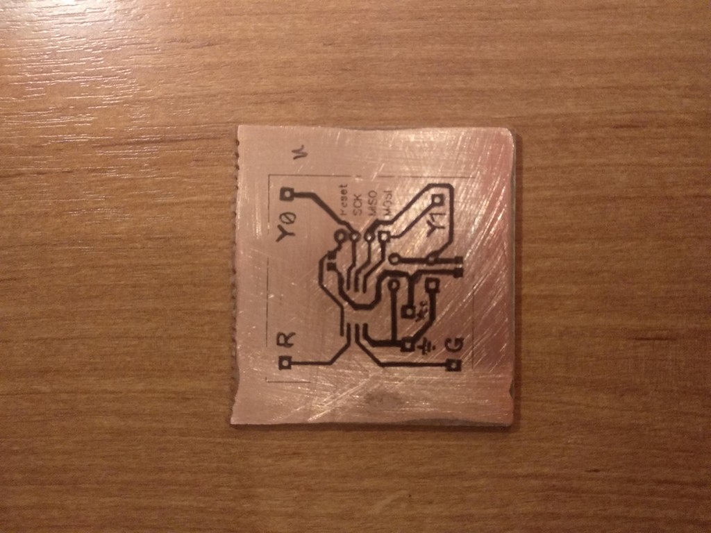
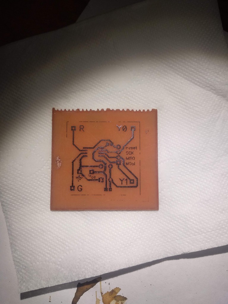
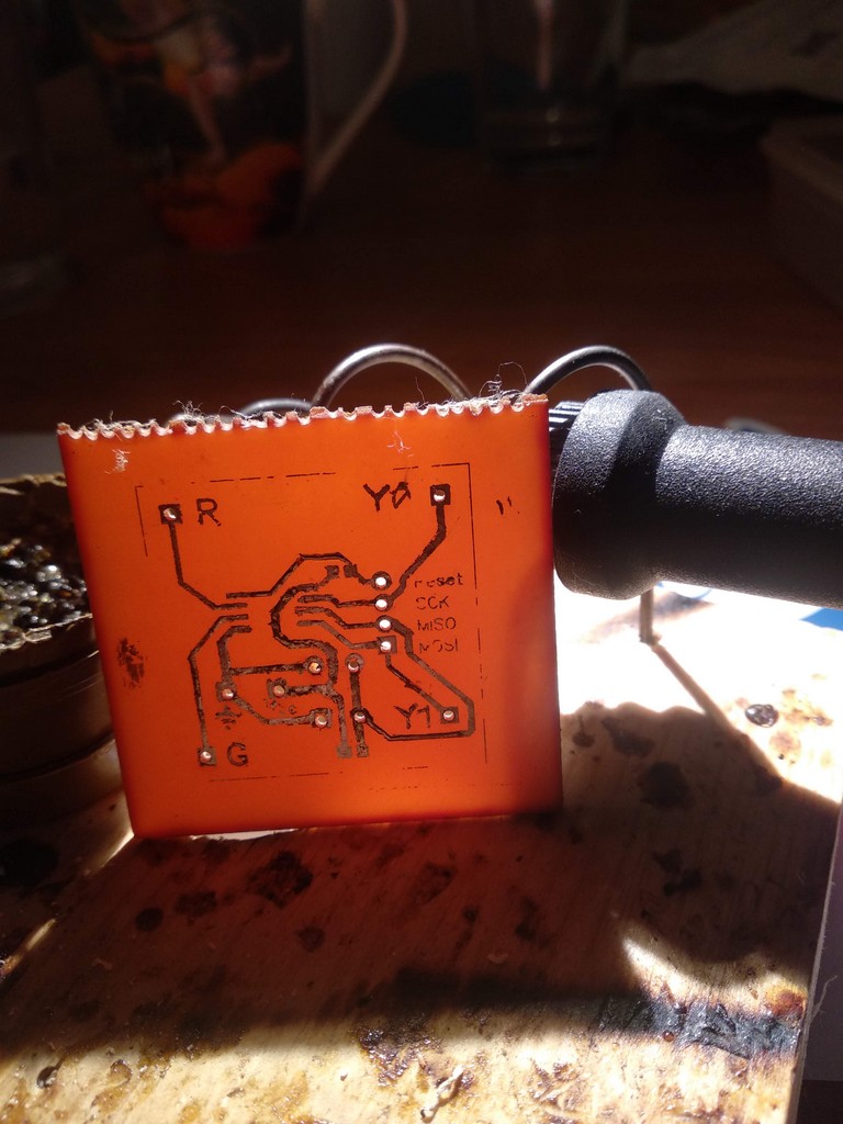
,DipTrace «» «PCB Layout», . , .
— .

, , .
( , 80- ).
CD .
, , , .
— .
: , .
, , . — , .
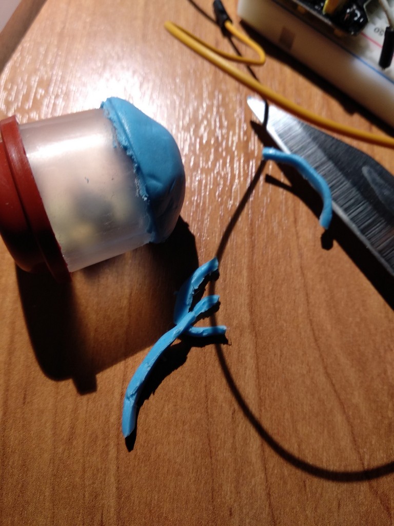
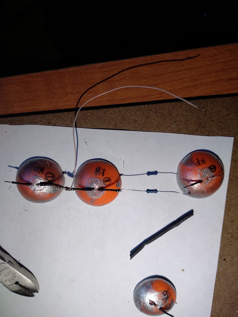
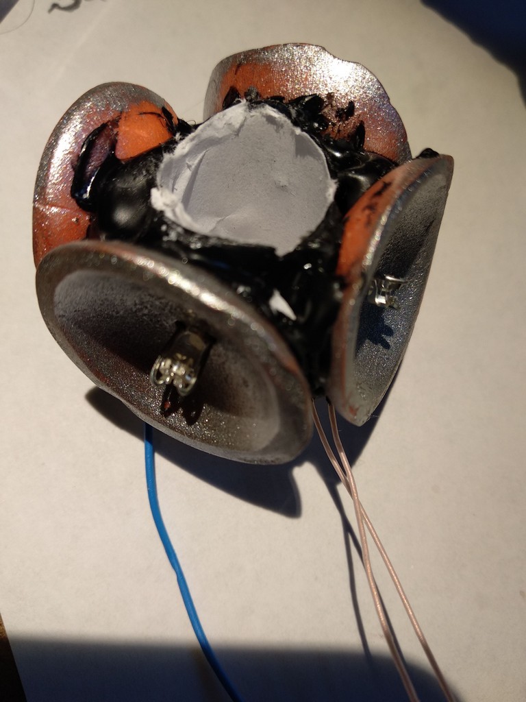
— . - - "Craft&Clay" 50- 70. , .
.
15 130 .
— .

— .
— .
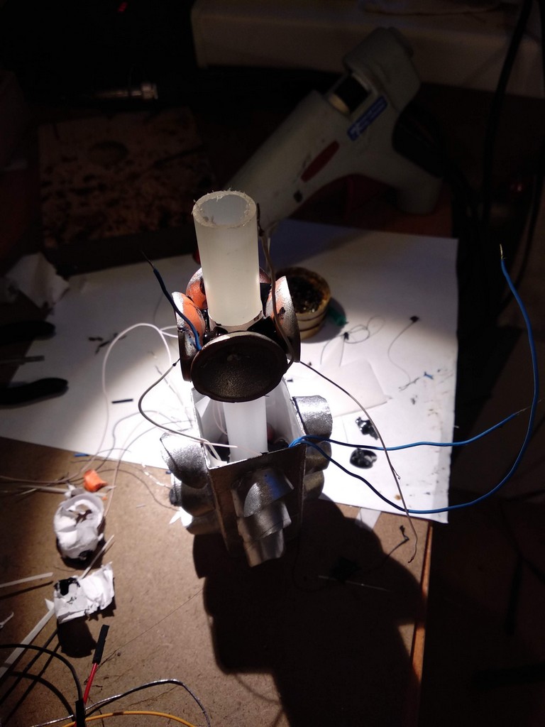
.

4 , 2-3 ,
, .

. , , , " ".
, .
KSP. — 4 LED 5 .

, , DC-DC 0.9-5 , .
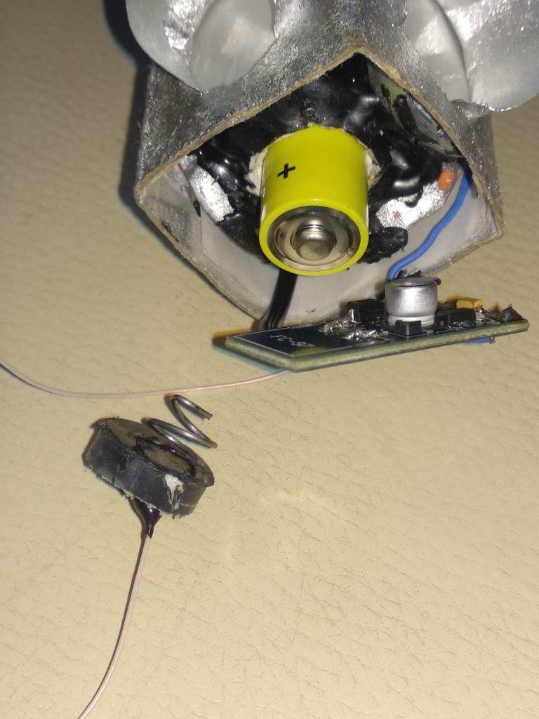
. , , .
, , , .
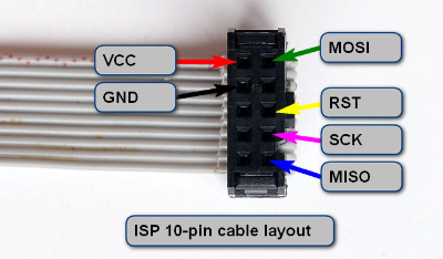
ISP 10- .
, , , - . , , " ". 1.5 , — . , .
| , | , %/ | , |
|---|
| CR1212 | 18 | 1 | 0.250 |
| CR1620 | 68 | 1 | 0.950 |
| CR2032 | 210 | 1 | 3 |
| NiCD AAA | 350 | 20 | 98 |
| NiMH AAA | 900 | 30 | 375 |
| NiCd AA | 1000 | 20 | 270 |
| Alkaline AAA | 1250 | 2 | 35 |
| NiMH AA | 2400 | 30 | 1000 |
| Alkaline AA | 2890 | 2 | 80 |
| Li-Ion | 4400 | 10 | 600 |
, . , , (2/100)2890/(2430) = 80 . , 2 , 32 ATtiny13.
: , GPIO, . — , ( 4 14 ""), , 40 .
, — . , . , : 5 DC-DC , , DC-DC 1.5 -> 5 . , - +-20%, .
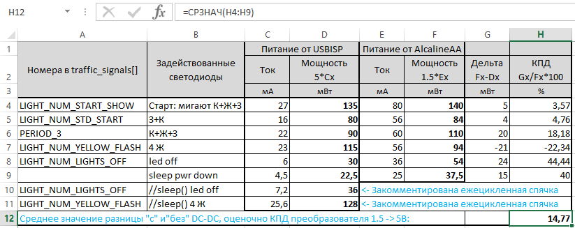
, "" 4-5 (5 ) , , 25 (1.5 ),
.. 2890 116 , . ATtiny13 POWER DOWN . , — . 20-50 , , Hi-Z, 1 . , DC-DC .
2 5 . : .
,
, :
- , — , R2, , . .
- . — 1/37 , .
- , , . POWER_DOWN 30 , , , .
- traffic_signals 8 4, . 4 pin — 1 DDR PORTB
- uint16_t signal_period flash_period — , , 1 .
- — ROM 2 , — - .
- /UART.
- main — — +50 ROM.
- 9,6 128 , .
.
: " ", , 8 , , «» .
.
Github, MIT.