Perhaps the familiar situation led me to develop my own telemetry - it worked, but it stopped. One evening, the car alarm unit ceased to perceive the keychain. I understood that first you need to try to rebind the keychain, for which it was necessary to perform a simple procedure, clearly following the instructions from the installation manual. The execution of the procedure became impossible, since the car alarm was in armed mode, which could be disabled by the Valet button by entering the service code.
I never tried to remember the service code, and even more so the master code. I tried unsuccessfully to recall several codes for memory. Within a few minutes I had to steal my car. The trill from the siren in my ears then stood for a long time, since the siren was installed in the passenger compartment. I don’t remember why I placed the siren exactly there - either out of my own laziness, or saw some sense in this. You know, from a personal experienced feeling, this can lead to severe confusion for an unprepared villain. To my deep regret, I had to dismantle the unit. I began to figure out what to do next and what to do about it. Who cares what happened in the end, I ask for a cat.
I had several hypotheses:
- Failures in the operation of the antenna module.
- Non-volatile memory failure in the main block. As a result, data about key fobs and their synchronization could be damaged.
- Failure of non-volatile memory of the transmitter. The consequences are similar to paragraph 2.
- Signal jamming in preparation for theft.
I checked the option with the presence of a signal jammer as soon as I moved to a safe place. Car alarms also did not respond to the key fob.
I turned to the dealer about the availability of those. the ability to reset service codes. I was told that there was no such opportunity and you would have to purchase a new kit for several thousand rubles. Yes, and it will be better if you install all this business with us - they said, giving away several thousand more. This answer did not surprise me at all, IMHO, of course! It is better for the dealer to sell a new kit than to carry out service. Then all of a sudden I felt how my mood improved dramatically, the thought arose to sort things out on my own, finding out along the way whether codes could be reset or not. In general, it is precisely such moments that prompt alternatives, reverse, development, and DIY. I challenged myself.
I did not start at all with digging in blocks, but with an alternative. While Pandora was lying in the closet, I tried to make my own module. I figured that if you develop your own car alarm module, it will be immediately cool, reliable, flexible and absolutely not difficult. What can I say, all this was sheer enthusiasm. I spent several weeks writing the firmware and prototyping the module. The process was completely creative. So, all of a sudden, an idea came to me and I realized it with pleasure. For example, already at the stage of a working prototype with the necessary reels, transistors and GSM, I suddenly wanted to add more GPS and Bluetooth. Well, why pull the cat by the tail? Let the module be cool right away, as I initially figured out, and I had to change the microcontroller to a bold one, since ATMega328 has only one UART port. To get something common from AVR and with three UARTs seemed to me an unrealistic undertaking. I did not like the option of implementing software UART, for the simple reason that the hardware is more reliable. I remember how STM32 already flashed with might and main in various articles on electronics and was available to order on AliExpress. Without hesitation, I wrote myself a pair of STM32F103, since it was a real 32-bit microcontroller with a large amount of memory and rich peripherals, and even more so with the necessary number of UART. I had no experience of programming STM32 at that time, but this only arose the interest of learning something new.
In anticipation of the arrival of microcontrollers, it was decided to postpone the prototype and not just wait, but check the hypotheses that remained.
Winter was approaching, and the car without “supervision” somehow did not inspire comfort. Everything continued until once I looked under the cover of the car alarm unit. Inside I discovered ATMega324! My joy knew no bounds, as it was an AVR, which means you could work with it properly. The first thing I did was to check the UART and SPI wiring. ATMega324 has 2 UART ports. One UART is connected to the shift register, and the second to the antenna module connector. The SPI circuits led me to an unsoldered block (in the photo near the quartz in the lower left corner of the board).

Quickly soldered the block and connected the programmer. Reading firmware and EEPROM resulted in empty dumps. Of course, the developer could not allow such a puncture. Checked the exchange between the unit and the antenna module. The TX line was clear at the time of the alarm. This could mean that the number of trinkets in memory is 0. The antenna module was not at all talkative. It also turned out that the microcontroller controls the power of the antenna module through a transistor switch. The input voltage was detected at the output of the key, and according to the instructions it should be + 5V. All this seemed a little strange to me. Maybe for this reason the antenna module was silent? I did not have any options for testing hypotheses. What about the fuse bits? Such a surprise! Firmware is allowed in firmware via the SPI interface. Well, now how to sit still exactly? That's right - write your firmware! It was such a hardcore option, because in addition to the firmware itself, I also had to ring the board.
Protective varnish interfered with the process, but armed with probes with a sharp tip, things went much better. It turned out that the varnish layer did not peel off, but gently pierced in the right places. The ringing board took two evenings.
Microcontroller port pinout I wrote a test firmware, flashed it, clicked with reels - great! The antenna module and keyfob were already useless. So if you can write the firmware for the car alarm unit, using all its ready-made circuitry and connection points in the car, it remains to solve the problem with the communication channel. I thought, what if you leave GSM and GPS in your project, throw out Bluetooth and screw it all to Pandora car alarms? Well, of course, this is the best option! Firstly, it was not necessary to prepare a complex board, the Pandora circuitry solved many problems, but I just needed to make an expansion module that would be connected instead of the standard antenna module. As you can understand, the waiting period for microcontrollers from China has not passed noticeably.
To connect all the modules to each other, I etched the board. She is very simple. In it, the finished GPS, GSM modules and the car alarm unit are connected to the UART ports of the STM32 microcontroller.

The filling of the module is located in the case of the power supply unit from the laptop.

The DC-DC converter did not want to be placed inside the enclosure and had to find a more spacious enclosure. As a result, the pencil case from the front of the SUPRA radio with a convenient snap-on mechanism was very suitable for the case.
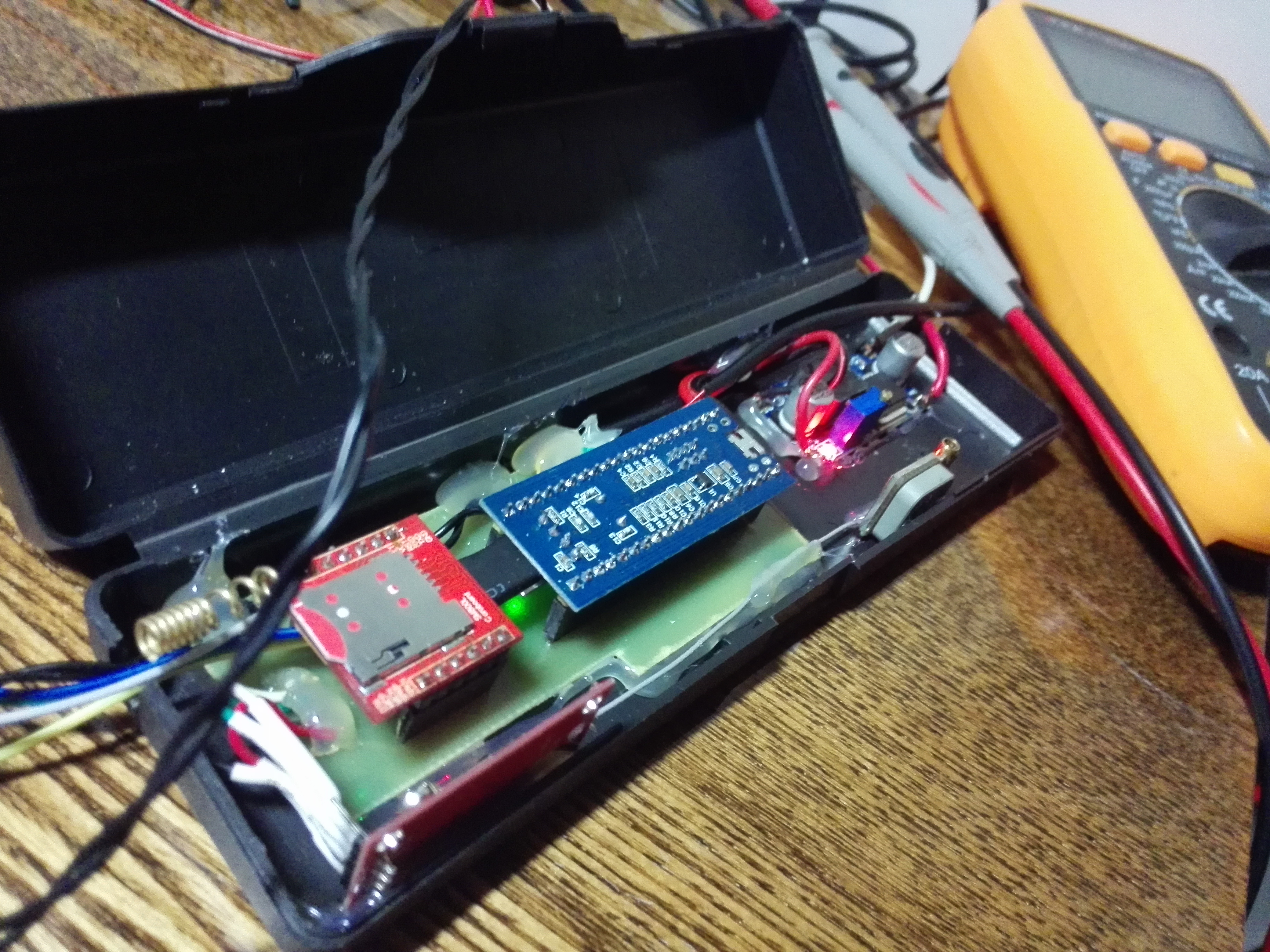
The board was coated with polyurethane varnish.
Components. Everything is simple here:
DC-DC Converter LM2596
GSM modem SIM800L (power 3.6-4.4)
GPS module NEO-6M (power 3.4-3.8)
A piece of PCB.
The required voltage for the modules forms a DC-DC converter. Its output voltage is set to 3.7 volts. The adjustment screw is coated with varnish to prevent it from shifting from vibrations.
I thought which peripherals I needed to support in the first place and I got the following list:
- Interior and engine temperature sensors.
- Accelerometer
- Voltmeter on-board network.
- Door limit switch input.
- Trunk limit switch input.
- Brake pedal limit switch input.
- The output to the ignition.
- Repeater relay output.
- Exit to the immobilizer lineman.
- Output to the interlock relay.
- Exit to the siren.
Conscious refusal of support:
- Exit to the central locking relay. The car is not wired to the door of the central lock.
- The tachometer input, as it simply does not make sense to connect to a hybrid car.
- The input of the hood limit switch, as it is missing from the vehicle.
Algorithms and functions that were implemented:
- Storing settings in EEPROM.
- Starting the engine using START-STOP technology.
- Activation of a keyless crawler with analog control (iDatalink).
- Remote engine start.
- Undervoltage control on the battery.
- Monitoring engine voltage.
- Arming / disarming (zone perimeter control).
- Control of limit switches for doors and trunk.
- Siren support.
- Support for signal lights (turn signal).
- Support silent mode.
- Support for external expansion card (telemetry module).
- Connection and transfer of states to the server.
- System management DTMF codes, in the absence of communication with the server.
- List of trusted numbers.
Feedback is implemented by calling to a trusted phone number from which the security mode was set.
System management was implemented through the Telegram bot:
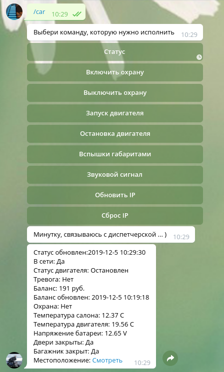
The bot also sends messages about critical conditions, such as:
- Low battery voltage.
- Battery voltage restored.
- Low engine temperature.
- High engine temperature.
In fact, home-made is already 3 years old and during this period I found out that:
- The homemade product was at the maximum uptime of about 80 days, then the device rebooted, since the GSM modem stopped even receiving calls.
- Stable operation in negative and high temperatures (from -40 to +40).
- Need to do digital bus support.
The possibility of flashing the Pandora DXL 3000 on the SPI bus is a vulnerability because it allows you to download software that can activate the outputs of the keyless immobilizer crawler and deactivate locks.
In general, the work done has given me tremendous experience. I studied the circuitry of car alarms, saw how to do it compactly and simply, and learned how to program STM32 microcontrollers. As a result, I made a product that I use myself. I was inspired and continued to develop the second version. The second version will be able to connect to digital buses to simplify and reduce the number of connection points, as well as implement a bypass standard immobilizer without external crawlers on IMMO-IMI chains.
Oh yes, all this time the system worked and continues to work on the family car Toyota Prius in the 20 body, which is rich in digital tires. Debugging support for the BEAN bus is in full swing.
PS: The second version was developed and is being tested on a 2007 Toyota Camry.
As a result, I see my project as an opportunity to create an open system for automotive telemetry.
Thanks for attention!