Barely grabbing crypto keys and copying Mifare key rings for intercoms is of course impossible, but it’s quite possible to assemble a device that will do this. I will not talk here about what Mifare is and go into technical details, I will only say that this technology is used now, for example, in intercoms, and in order to copy an intercom keychain, you need to know the cryptographic keys with which it was closed.
Attention! This article is for educational purposes only. We remind you that any penetration into information systems can be prosecuted by law.
Many people interested in MIfare technology probably have the simplest Mifare card / key fob reader / writer, consisting of a PN532 module and a USB-UART adapter:

By a simple and inexpensive refinement, this device can be made to capture from
Reader authentication data, with the help of which the crypto keys are calculated, so necessary for reading and copying. There are also commercially available devices for this purpose - SMKey, Proxmark3, Chameleon and some more. These are devices with many functions, convenient, but not cheap.
I bring to your attention a more budget option based on a similar “small gentleman's set” from the PN532 module and a USB-UART adapter, which allows you to capture data from a Mifare reader, such as an intercom, and calculate the cryptographic keys with which the reader refers to the tag.
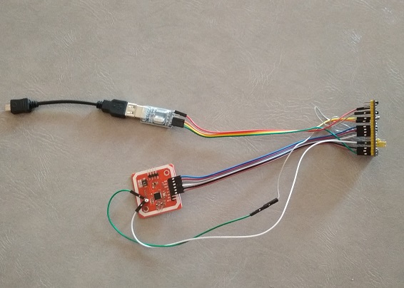
The developed device basically has an inexpensive, “popular” debugging board based on the STM32F103C8T6 processor, also called “BluePill” with the PN532 module and USB-UART adapter connected to it. This unit is connected via USB-OTG cable to a smartphone on Android. All this is assembled in a mock-up version without soldering, with the help of jumpers, and has something like this, although it is unpresentable, but quite working:
The assembly diagram is very simple and is presented in text form:
PN532 ___________________STM32F103C8T6
SCK _____________________ PA5 (SPI1_SCK)
MISO ____________________ PA6 (SPI1_MISO)
MOSI ____________________ PA7 (SPI1_MOSI)
SS ______________________ PB0 (GPIO_OUTPUT)
SIGIN ___________________ PB11 (TIM2_CH4)
SIGOUT __________________ PA12 (TIM1_ETR)
SIGOUT __________________ PA0 (TIM2_ETR)
VCC _____________________ + 5V
GND_____________________GND
USB-UART ________________ STM32F103C8T6
RX ______________________ PA9 (USART1_TX)
TX ______________________ PA10 (USART1_RX)
+ 5V _____________________ + 5V
GND_____________________GND
IMPORTANT! PN532 interface switches must be set to SPI mode! You can flash STM32 using the FlashLoaderDemonstrator utility through the existing USB-UART adapter.
Here is a demo of capturing a crypto key from a doorphone reader simulator (Arduino + PN532):
Since IronLogic (IL) readers, for working with whom this device was developed, are trying to read a tag with a crypto key calculated on the basis of the UID of this tag, this UID must first be set. You can do this in two ways - manually or read from the tag. After that, we make a capture and wait for the calculation of crypto keys.
The next tab of the “Record on Classic” program uses the ability of earlier versions of IL readers to write copies to cheap Mifare Classic blanks. This method is based on the fact that the IL reader after authorization sends to the intercom not the original UID of the tag, but the information recorded in the first block (in the general case, the same as the UID of the original). To do this, we need to capture and calculate the crypto key of the label, which will serve as the blank, close the zero sector with it, and write four bytes of the UID of the label, which serves as a prototype, into the first block of this label. To do this, we don’t even need to grab the original cryptocurrency key and remove its dump, it’s enough to find out its UID, but this is only true if the original is “original” and not a copy, then you still have to read the first block and already write to a copy. To make it clearer, consider this example - suppose we want to make a copy of the original key with UID 0xEBD52AC5, which is also written in the first block of the original, on a regular Mifare Classic label with a UID, say 0x12345678. To do this, with the help of the presented device, aptly called by one comrade Shaitan-Mashina, we find the cryptocurrency for this UID and for the particular object (entrance, home ...) that we need. Let the crypto key be 0xABCDEF098765, then edit the zero sector of the copy dump as follows:
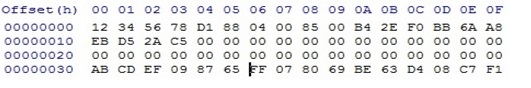
In the first block, we write the UID of the original 0xEBD52AC5, and in the third block the six bytes of the crypto key found for this workpiece are 0xABCDEF098765. We write the dump to the blank, and get a copy of the intercom key. Something like this SMKey makes copies of IronLogic to regular Mifare Classic, and this is what this recording program does. In the “Code” field, we manually enter or read 4 bytes of UID from the original key, which will be recorded in the 1st block of the copy. We start and then follow the prompts of the program. First we read the UID of the workpiece, then we bring the device to the intercom and capture authentication data. After the calculation is completed, the program will offer to bring the blank for data recording. If more than one cryptographic key is found, then after recording the first option, it will be given the opportunity to verify the received copy. If the copy does not fit, then you should try the next calculated key, or erase (restore) the blank for future use. A copy may also not work because the code that is written in the 1st block of the copy was incorrectly defined - for example, if you try to write the real UID of not the original key fob, but a copy made using the above method. In this case, you should not use the UID labels, and data from the 1st block, which can be obtained in the section "Copying a sector".
This method will also not work for the latest versions of IL reader software. In this case, a copy can be made by copying the entire 0th sector (4 blocks) onto a workpiece that allows you to record the 0th sector using the “Copy Sector” application section. Here, we also first find the original cryptocurrency key, read its zero sector and then write to the blank. Due to the lack of OTP and OTP-2.0 blanks at hand, this feature has so far been tested only on ZERO blanks, although newer versions of readers require the use of OTP-2.0.
Well, for starters - the “Record UID” section of the application allows you to change the UID, restore the damaged 0th block, and reset the crypto keys of ZERO blanks to default.
So - to summarize briefly. To make such a device, we purchase or look for a PN532 module, any of the USB - UART adapters FTDI, PL2303, CH340 or CP2102, a debug board STM32F103C8T6, a half dozen jumpers, a USB-OTG adapter and a smartphone (tablet) on Android with OTG. We assemble the device itself according to the above diagram, flash * .bin with the STM32 file and install * .apk application from the
archiveon a smartphone. For correct operation, the application on the smartphone must be launched when the USB-UART adapter is connected, either by default, or by manual selection, otherwise the application will not get access to the adapter.
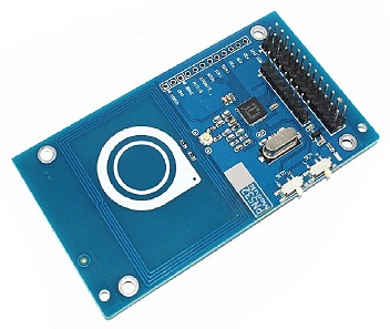
I want to say a few words about the PN532 module - not all of these modules are “equally useful”! Of the three modules (such as in the photo above) that I purchased, one didn’t read and write tags, especially ZERO and OTP-2.0, but it worked normally in passive mode with intercom readers, the other behaved exactly the opposite, and only the third more- less cope with both tags and intercoms (though worse than the first two). Maybe I’m out of luck and this particular batch of modules turned out to be of not the best quality, but other people complain about them. However - to someone as lucky. What am I saying? PN532 modules appeared on sale for a slightly different layout, which are more expensive, but, according to reviews, they do not have such problems:
If someone comes across PN532, which doesn’t write or read labels well, I can recommend adding an RC522 module to the device, which is worth a penny, but performs its functions perfectly, according to the following scheme:
RC522____________________STM32F103C8T6
RST ______________________ PB12 (GPIO_OUTPUT)
SCK ______________________ PB13 (SPI2_SCK)
MISO _____________________ PB14 (SPI2_MISO)
MOSI _____________________ PB15 (SPI2_MOSI)
SDA ______________________ PA8 (GPIO_OUTPUT)
VCC ______________________ + 5V
GND______________________GND
In this case, the PN532 will only work when capturing data from the reader, and the whole burden of working with tags will fall on the shoulders of the RC522.
In conclusion, I want to say that the performance of the device in real conditions was tested only on IronLogic readers of the very first generation, without ZERO, OTP, OTP-2.0 filters. Other versions simply do not have access, so for more modern IL readers, software development will be required, and, of course, the presence of these readers.
Archive