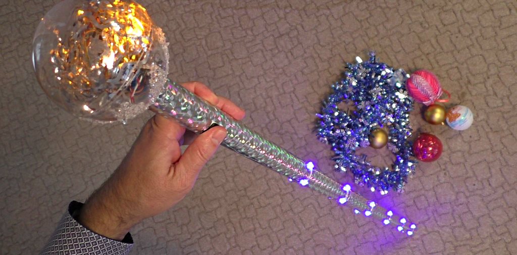
Every year on December 31, I, in the costume of Santa Claus, and my wife, in the role of the Snow Maiden, drive around the city to my friends with congratulations. Since the New Year is coming soon, I decided to check if everything is ready for me and took out my long-worn staff from the basement. To my surprise, after lying in the basement for a year, he worked properly even now! His battery is still somehow charged! The staff is not very bright, but it glows. Of course, I’ll have to recharge, and I’m watching one LED stops working, but this is fixable - we’ll fix it.
I made this staff back in 2012, and since then it has served me faithfully. The thing is quite simple, but very effective, especially the children rejoice at it. He is almost like a Jedi sword - only a staff, and for the real Santa Claus - this is a necessary thing. I decided to write about him here on Habré - suddenly someone will be inspired by the idea and make this for himself by the New Year, there is still time.
To make a staff you will need:
- a piece of plastic water pipe 1.3 meters;
- a little shiny self-adhesive for decoration;
- a piece of UTP-5 network cable or any other suitable cable;
- blue LEDs, at least 24 pieces;
- battery;
- power button;
- any small microcontroller or FPGA board that has something that you can program;
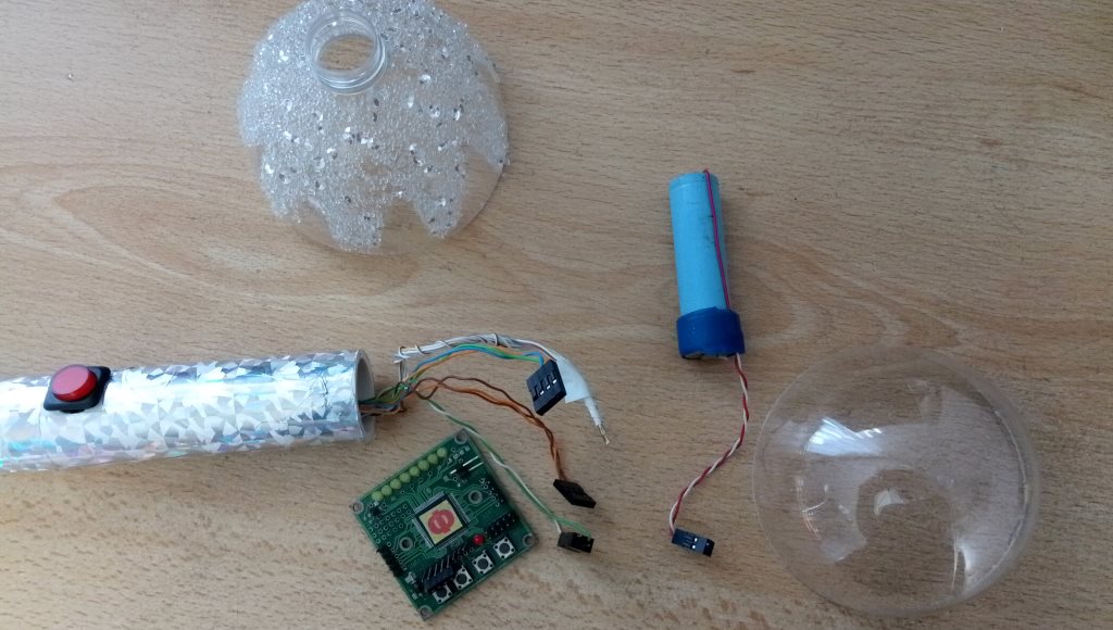
- a large ball-Christmas tree toy that can be divided in half so that both the board and the battery can be hidden in it.
The necessary parts are visible in this photo:
The device of the staff is very simple. There is especially nothing to write about. We take a white plastic water pipe and drill several holes at the same distance of 200 mm. I got 6 holes.
We dissolve the UTP-5 cable into several twisted pairs. Six pairs of wires are needed. We launch them into the holes and output through one end of the pipe, to where the magic ball of the staff will be. Where pairs of wires go into the holes of the pipe, we clean them and tightly wrap around the pipe at a certain distance from each other. We solder. To the resulting "bus" in a circle of the staff solder in parallel 4 blue LEDs:

At the top of the pipe, you need to drill a larger hole and paste the control board power button there:

I have the Mars rover scarf as a control board. Here is the FPGA of Altera MAX II, and since the board was originally intended to connect low-power toy engines, the chip outputs on the board are combined in 10 pieces to give a little more current. There are just 6 of such combined pins on the board - these are the “signals” of the board f0, f1, f2, f3, f4, f5. So I can directly power the LEDs from these conclusions without fear of burning the output of the FPGA. Also on the board itself there are 8 yellow LEDs - they can also be ignited. If the ball on the top of the staff is translucent, then this will also add a visual effect.
If you use Arduino, for example, in a staff, you may have to solder a small scarf with transistor keys to control many LEDs, since it is better not to take more than 10-15mA from one pin of the microcontroller, but we need much more for LEDs.
The board needs to be flashed with the control program. The idea is that when you press the button on the staff, the board turns on and it immediately starts to light the lights on the staff. Then who has what fantasy. I first light up in turn all the LEDs from the first row to the sixth, and then I turn off the turns from the sixth to the first.
Verilog HDL code will probably explain better what I mean:
module effect( input wire clk, input wire mclk, output wire [7:0]leds, output wire f0, output wire f1, output wire f2, output wire f3, output wire f4, output wire f5 ); reg [3:0]cnt; reg [5:0]bits; initial begin bits= 6'h00; cnt = 4'h0; end always @(posedge clk) if(cnt==11) cnt<=0; else cnt <= cnt + 1'b1; always @* begin case(cnt) 4'h0: bits = 6'b000001; 4'h1: bits = 6'b000011; 4'h2: bits = 6'b000111; 4'h3: bits = 6'b001111; 4'h4: bits = 6'b011111; 4'h5: bits = 6'b111111; 4'h6: bits = 6'b011111; 4'h7: bits = 6'b001111; 4'h8: bits = 6'b000111; 4'h9: bits = 6'b000011; 4'ha: bits = 6'b000001; default: bits = 6'b000000; endcase end assign f0 = bits[0] & mclk; assign f1 = bits[1] & mclk; assign f2 = bits[2] & mclk; assign f3 = bits[3] & mclk; assign f4 = bits[4] & mclk; assign f5 = bits[5] & mclk; assign leds = {bits[5],bits[5],bits[4],bits[3],bits[2],bits[1],bits[0],bits[0]}; endmodule
This is not a top-level module, it is an effect.v module. From the top module, two clock frequencies of clk ~ 40Hz are fed here - this frequency determines the speed of the effect and the second frequency mclk ~ 320Hz, eight times higher. The mclk signal additionally modulates the outputs again, so that they are not always turned on, so that the LEDs do not shine so brightly and the chip does not heat up.
I don’t know if I need to memorize this article. But just in case, I’ll write that the above Verilog code can be fully simulated using this testbench:
`timescale 1ms / 1us module tb; reg clock = 1'b0; always #10 clock = ~clock; reg [3:0]counter=0; always @(posedge clock) counter <= counter+1; wire [7:0]wleds; wire wf0,wf1,wf2,wf3,wf4,wf5; effect inst( .clk( counter[2] ), .mclk( clock ), .leds( wleds ), .f0( wf0 ), .f1( wf1 ), .f2( wf2 ), .f3( wf3 ), .f4( wf4 ), .f5( wf5 ) ); initial begin $dumpfile("out.vcd"); $dumpvars(0,tb); #10000; $finish(); end endmodule
How exactly is the simulation of projects can be read, for example,
here .
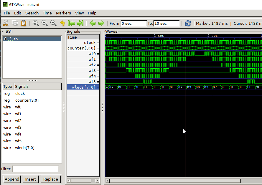
Well, according to the results of the simulation, you can get these timing diagrams of signals:
If you plan to do this project on Arduin - this is also possible. I'm really not a big connoisseur of Arduina, but it seems to me that the code may look something like this:
int start_pin = 2; int end_pin = 8; void setup() { for (int i = start_pin; i< end_pin; i++ ) pinMode(i, OUTPUT); } void loop() { for (int i = start_pin; i< end_pin; i++ ) { digitalWrite(i, HIGH); delay(250); } for (int i = start_pin; i< end_pin; i++ ) { digitalWrite(i, LOW); delay(250); } }
The result should be something like this:
Despite the fact that the project as a whole is very simple, the spectators and casual passers-by on December 31st are invariably delighted. Especially when you get out of the car in a suit of Santa Claus on a snowy street, you approach a random passerby and illuminate the way with a staff, you give a mandarin duck.