مقدمة
كطلاب في السنة الأولى من جامعة Innopolis ، أتيحت لنا الفرصة لعمل مشروعنا الخاص في هندسة الكمبيوتر. اقترحت علينا الجامعة العديد من المشاريع واخترنا عمل آلة حاسبة قائمة على المكدس مع تدوين عكسي. أحد متطلبات المشروع هو استخدام لوحة FPGA المقدمة من الجامعة.
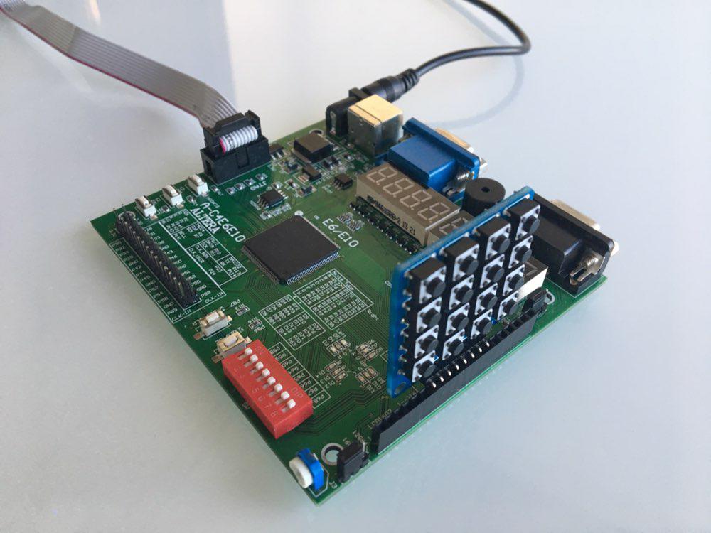
بصفتنا مجلسنا ، اخترنا Cyclon IV. لذلك ، كان علينا كتابة رمز على لغة وصف الأجهزة. في الدورة درسنا فيريلوج ، لذلك اخترناها. أيضا ، لدى الجامعة وحدات إضافية لـ FPGA ، مثل numpad ، لذلك قررنا استخدامها في مشروعنا.
في هذه المقالة ، نريد مشاركة معرفتنا حول FPGA و Verilog ، كما نقدم لك برنامجًا تعليميًا لتكرار مشروعنا.
التصميم الأساسي
شكلنا مجموعة من شخصين ونظمنا اجتماعنا الأول. هناك ناقشنا التصميم الأساسي ، وتقسيم مسؤولياتنا ووضعنا خطة قصيرة مع المواعيد النهائية. هذا ما توصلنا إليه. نحن بحاجة إلى:
- تنفيذ المكدس في Verilog
- تعلم كيفية العمل مع اللوحة
- نفذ الإخراج من خلال شاشة عرض مكونة من 8 أجزاء موجودة على لوحة FPGA
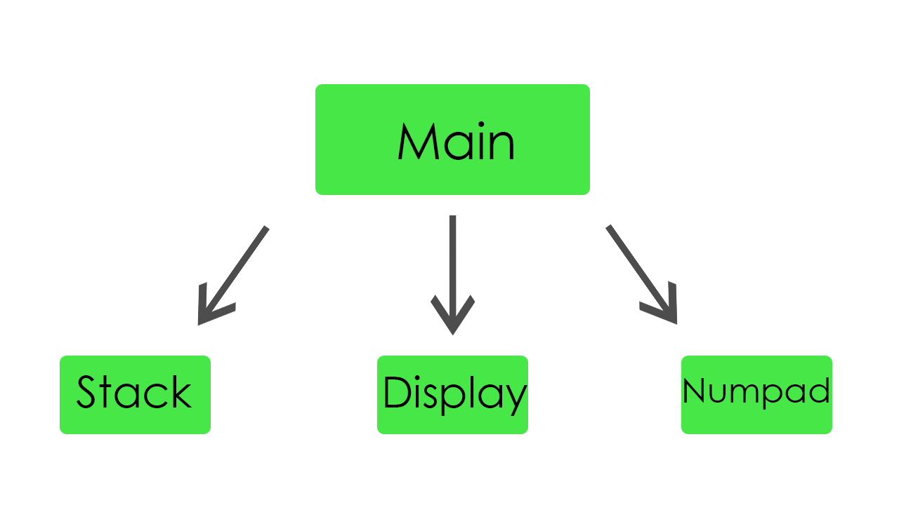
- اصنع وحدة رئيسية تربط جميع الوحدات معًا
لقد اختار كل عضو من أعضاء الفريق نفسه وحدة للكتابة. كانت مهمة الترتيب الأول هي تنفيذ التكديس والإخراج والإدخال. كما تم تحديده ، بدأنا العمل.
المكدس
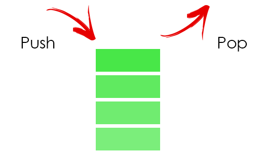
في المكدس ، نقوم بتخزين جميع المعاملات لدينا. لتخزينها ، خصصنا 32 كلمة من الذاكرة.
كود وحدة المكدسmodule stack( //Just 50 MHz clock input clock, //Reset signal input reset, //PUSH operation control signal input push, //POP operation control signal input pop, //SWAP operation control signal input swap, //UPDATE operation control signal input write, //Value to write input [31:0] value, //Top element output [31:0] top, //Second element from stack top output [31:0] next, //Total elements count output [5:0] count, //Stack overflow error output error ); //Stack memory for 32 words reg [31:0] memory [0:31]; //Stack pointer on top element, indexing from 0 reg [5:0] pointer = 0; //First element by default is 0 initial memory[0] = 0; //Top stack element assign top = memory[pointer]; //Second element if such exists, 0 otherwise assign next = pointer == 0 ? 0 : memory[pointer - 1]; //Stack elements count assign count = pointer[4:0] + 1; //Stack overflow signal assign error = pointer[5]; always @(posedge clock) begin //Reseting if (reset) begin memory[0] <= 0; pointer <= 0; end //Remove one element form stack if (pop) pointer <= pointer - 1; //Swaps top and next elements if (swap) begin memory[pointer] <= memory[pointer - 1]; memory[pointer - 1] <= memory[pointer]; end //Update top element if (write) memory[pointer - pop] <= value; //Push new zero element on top if (push) begin pointer <= pointer + 1; //Here pointer is still not updated, so +1 memory[pointer + 1] <= 0; end end endmodule
إنها مجرد كومة عادية. إذا تم دفع قيمة جديدة إليه ، فإنه يزيد المؤشر ويضع هذه القيمة في أعلى المكدس. إذا ظهرت قيمة من المكدس ، فإنه يقلل المؤشر ويحدث العنصر العلوي.
من أجل الراحة ، أضفنا زر إعادة تعيين ، من أجل الحصول على فرصة لإعادة تشغيل برنامجنا أثناء التنفيذ. أيضا ، لتصحيح الأخطاء تمت إضافة فرصة لالتقاط خطأ تجاوز سعة المكدس.
العرض
في هذه الوحدة ، قمنا بتنفيذ جميع وظائف الشاشة. إنه قادر على إظهار نتائج حساباتنا ديناميكيًا وكذلك قيم الإدخال.

هنا هو رمز العرض module display_bcd ( //Just 50 MHz clock input clock, //Switching hexademical and decimal representations input show_in_hex, //Asserted if something is going wrong, displaing error message input error, //Value to be displayed in binary format input [31:0] value, //Segments of display output [7:0] control, //LEDs of one segment output [7:0] leds ); // ###0### // # # // # # // 5 1 // # # // # # // ###6### // # # // # # // 4 2 // # # ### // # # #7# // ###3### ### //All representation of used symbols parameter D_0 = 8'b00111111; parameter D_1 = 8'b00000110; parameter D_2 = 8'b01011011; parameter D_3 = 8'b01001111; parameter D_4 = 8'b01100110; parameter D_5 = 8'b01101101; parameter D_6 = 8'b01111101; parameter D_7 = 8'b00000111; parameter D_8 = 8'b01111111; parameter D_9 = 8'b01101111; parameter D_DOT = 8'b10000000; parameter D_A = 8'b01110111; parameter D_B = 8'b01111100; parameter D_C = 8'b01011000; parameter D_D = 8'b01011110; parameter D_E = 8'b01111001; parameter D_F = 8'b01110001; parameter D_R = 8'b01010000; parameter D_O = 8'b01011100; parameter D_MINUS = 8'b01000000; parameter D_EMPTY = 8'b00000000; parameter D_E_CODE = 14; parameter D_R_CODE = 16; parameter D_O_CODE = 17; parameter D_MINUS_CODE = 18; parameter D_EMPTY_CODE = 31; //Delay counter, delaying 8192 clock cycles ~ 0.16 ms reg [12:0] counter = 0; //Saved Binary-Coded Decimal reg [31:0] r_bcd; //Number of segment that is active on current iteration reg [2:0] ctrl = 0; //Current digit shown on the current segment reg [4:0] digit; //Asserted for 1 cycle when conversion to Binary-Coded Decimal is done wire converted; //Intermediate Binary-Coded decimal value wire [31:0] bcd; //Decoded number digits wire [31:0] digits; //Number sign wire sign; //Digits from unsigned numbers wire [31:0] unsigned_number; bcd_convert #(32, 8) bcd_convert( .i_Clock(clock), .i_Binary(unsigned_number), .i_Start(1'b1), .o_BCD(bcd), .o_DV(converted)); //Get number sign assign sign = value[31]; //Get unsigned number assign unsigned_number = sign ? -value : value; //Switching final number representation assign digits = show_in_hex ? unsigned_number : r_bcd; //Constolling segments assign control = ~(1 << ctrl); reg [7:0] r_leds; //Controlling LEDs assign leds = ~r_leds; always @(posedge clock) begin case (digit) 0: r_leds <= D_0; 1: r_leds <= D_1; 2: r_leds <= D_2; 3: r_leds <= D_3; 4: r_leds <= D_4; 5: r_leds <= D_5; 6: r_leds <= D_6; 7: r_leds <= D_7; 8: r_leds <= D_8; 9: r_leds <= D_9; 10: r_leds <= D_A; 11: r_leds <= D_B; 12: r_leds <= D_C; 13: r_leds <= D_D; 14: r_leds <= D_E; 15: r_leds <= D_F; 16: r_leds <= D_R; 17: r_leds <= D_O; 18: r_leds <= D_MINUS; default: r_leds <= D_EMPTY; endcase if (error) //Display error message case(ctrl) 0: digit <= D_R_CODE; 1: digit <= D_O_CODE; 2: digit <= D_R_CODE; 3: digit <= D_R_CODE; 4: digit <= D_E_CODE; 5: digit <= D_EMPTY_CODE; 6: digit <= D_EMPTY_CODE; 7: digit <= D_EMPTY_CODE; endcase else //Select current digit case(ctrl) 0: digit <= digits[3:0]; 1: digit <= digits[31:4] ? digits[7:4] : D_EMPTY_CODE; 2: digit <= digits[31:8] ? digits[11:8] : D_EMPTY_CODE; 3: digit <= digits[31:12] ? digits[15:12] : D_EMPTY_CODE; 4: digit <= digits[31:16] ? digits[19:16] : D_EMPTY_CODE; 5: digit <= digits[31:20] ? digits[23:20] : D_EMPTY_CODE; 6: digit <= digits[31:24] ? digits[27:24] : D_EMPTY_CODE; 7: digit <= sign ? D_MINUS_CODE : (digits[31:28] ? digits[31:28] : D_EMPTY_CODE); endcase //Increase current delay counter <= counter + 1; //Delay is done, increase segment number if (counter == 13'b1000000000000) ctrl <= ctrl + 1; //Save converted Binary-Coded Decimal if (converted) r_bcd <= bcd; end endmodule
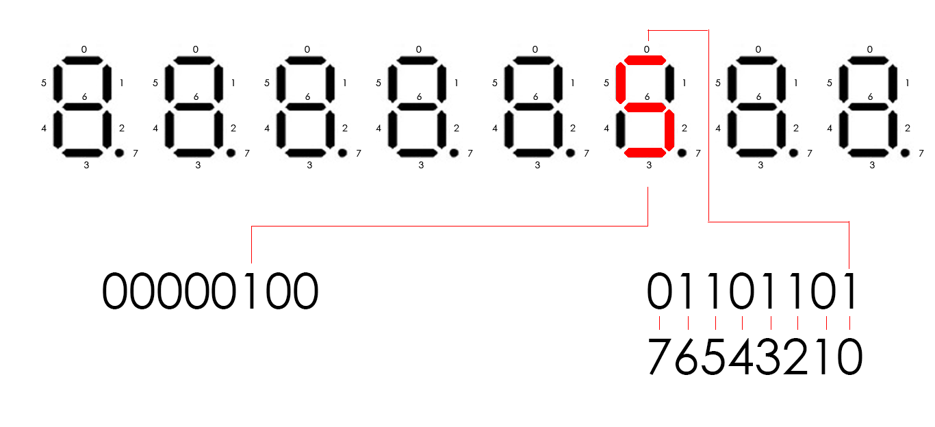
يحتوي Cyclone IV على ثماني شاشات عرض من ثمانية أجزاء. يتم التحكم فيها بواسطة 16 دبابيس. تتحكم ثماني دبابيس في أجزاء في كل شاشة عرض (لنطلق عليها اسم LED) وثمانية دبابيس أخرى تتحكم في أي شاشة ستكون نشطة (فقط اتصل بها بالتحكم). على سبيل المثال ، إذا احتجنا إلى إظهار الرقم 5 على الشاشة الثالثة ، فيجب أن يكون عنصر التحكم 00000100 وأن يكون LED 01101101 (وفقًا للمخطط في الرمز). لعرض عدة أرقام مختلفة على شاشات عرض مختلفة ، نحتاج إلى إضاءة كل شاشة بشكل دوري. لذلك ، كل 8192 دورة ساعة ، نتحرك يسارًا منطقيًا بمقدار 1 بت من ناتج التحكم الخاص بنا ، والذي يساوي مبدئيًا 00000001. عندما نقوم بتحريكه ، نغير الرقم الذي سيتم عرضه حاليًا. يحدث ذلك بسرعة كبيرة ، بحيث لا يمكن لعيننا رؤية التغييرات ، وبالتالي ، يمكننا إظهار أرقام مختلفة في كل شاشة.
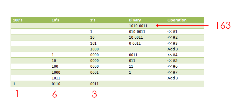
بينما ننتقل إلى هذا الرقم الثنائي للوحدة النمطية ، نحتاج إلى تمثيله بطريقة أو بأخرى كأرقام منفصلة. لهذا الغرض ،
وجدنا وحدة نمطية تستخدمها ، باستخدام خوارزمية dabble مزدوجة. يأخذ كمدخل رقمنا الثنائي ويعيده على شكل عشري مشفر ثنائي (4 بت لكل رقم).
هنا هو رمز لها module bcd_convert #(parameter INPUT_WIDTH, parameter DECIMAL_DIGITS) ( input i_Clock, input [INPUT_WIDTH-1:0] i_Binary, input i_Start, // output [DECIMAL_DIGITS*4-1:0] o_BCD, output o_DV ); parameter s_IDLE = 3'b000; parameter s_SHIFT = 3'b001; parameter s_CHECK_SHIFT_INDEX = 3'b010; parameter s_ADD = 3'b011; parameter s_CHECK_DIGIT_INDEX = 3'b100; parameter s_BCD_DONE = 3'b101; reg [2:0] r_SM_Main = s_IDLE; // The vector that contains the output BCD reg [DECIMAL_DIGITS*4-1:0] r_BCD = 0; // The vector that contains the input binary value being shifted. reg [INPUT_WIDTH-1:0] r_Binary = 0; // Keeps track of which Decimal Digit we are indexing reg [DECIMAL_DIGITS-1:0] r_Digit_Index = 0; // Keeps track of which loop iteration we are on. // Number of loops performed = INPUT_WIDTH reg [7:0] r_Loop_Count = 0; wire [3:0] w_BCD_Digit; reg r_DV = 1'b0; always @(posedge i_Clock) begin case (r_SM_Main) // Stay in this state until i_Start comes along s_IDLE : begin r_DV <= 1'b0; if (i_Start == 1'b1) begin r_Binary <= i_Binary; r_SM_Main <= s_SHIFT; r_BCD <= 0; end else r_SM_Main <= s_IDLE; end // Always shift the BCD Vector until we have shifted all bits through // Shift the most significant bit of r_Binary into r_BCD lowest bit. s_SHIFT : begin r_BCD <= r_BCD << 1; r_BCD[0] <= r_Binary[INPUT_WIDTH-1]; r_Binary <= r_Binary << 1; r_SM_Main <= s_CHECK_SHIFT_INDEX; end // Check if we are done with shifting in r_Binary vector s_CHECK_SHIFT_INDEX : begin if (r_Loop_Count == INPUT_WIDTH-1) begin r_Loop_Count <= 0; r_SM_Main <= s_BCD_DONE; end else begin r_Loop_Count <= r_Loop_Count + 1; r_SM_Main <= s_ADD; end end // Break down each BCD Digit individually. Check them one-by-one to // see if they are greater than 4. If they are, increment by 3. // Put the result back into r_BCD Vector. s_ADD : begin if (w_BCD_Digit > 4) begin r_BCD[(r_Digit_Index*4)+:4] <= w_BCD_Digit + 3; end r_SM_Main <= s_CHECK_DIGIT_INDEX; end // Check if we are done incrementing all of the BCD Digits s_CHECK_DIGIT_INDEX : begin if (r_Digit_Index == DECIMAL_DIGITS-1) begin r_Digit_Index <= 0; r_SM_Main <= s_SHIFT; end else begin r_Digit_Index <= r_Digit_Index + 1; r_SM_Main <= s_ADD; end end s_BCD_DONE : begin r_DV <= 1'b1; r_SM_Main <= s_IDLE; end default : r_SM_Main <= s_IDLE; endcase end // always @ (posedge i_Clock) assign w_BCD_Digit = r_BCD[r_Digit_Index*4 +: 4]; assign o_BCD = r_BCD; assign o_DV = r_DV; endmodule // Binary_to_BCD
تعمل هذه الوحدة مع خوارزمية مثيرة للاهتمام للغاية. ينقل كل البتات في الرقم إلى اليسار واحدًا تلو الآخر ، وإذا كانت أول 4 بتات أكبر من 4 بتدوينًا عشريًا ، فإنها تضيف العلامة العشرية 3 إليها.
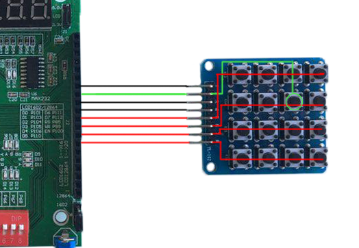
لوحة
تعمل هذه الوحدة مع اللوحة. يقرأ القيمة من لوحة المفاتيح ويمررها إلى الوحدة الرئيسية. لدينا حالتان من لوحة المفاتيح. يمكن تبديلها بالضغط على أحد الأزرار الموجودة في fpga.
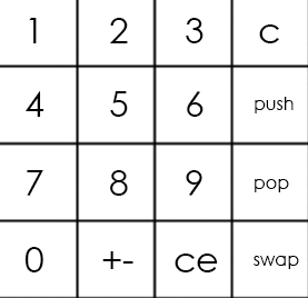
تبدو لوحة المفاتيح الرئيسية كما يلي:
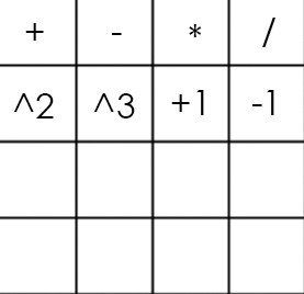
والبديل من هذا القبيل:
كود numpad module numpad ( //Just 50 MHz clock input clock, //Alternative keyboard input alt_key, //Alternative keyboard indicator output alt_led, //Numpad rows input [3:0] rows, //Numpad columns output [3:0] columns, //State change description [5:5] - is_changed, [4:4] - keyboard, [3:0] - button output [5:0] value ); // col 0 col 1 col 2 col 3 // // ############################# // # # # # # // # 1(0) # 2(4) # 3(8) # A(12)# row 0 // # # # # # // ############################# // # # # # # // # 4(1) # 5(5) # 6(9) # B(13)# row 1 // # # # # # // ############################# // # # # # # // # 7(2) # 8(6) # 9(10)# C(14)# row 2 // # # # # # // ############################# // # # # # # // # 0(3) # F(7) # E(11)# D(15)# row 3 // # # # # # // ############################# parameter BTN_EMPTY = 6'b000000; //Previous pressed button reg [5:0] prev = 0; //Current pressed button reg [5:0] cur = 0; //Current column number reg [1:0] col = 0; //Counter for delay reg [8:0] counter = 0; //Rows pressed flags reg [3:0] pressed = 0; //Is alternative keyboard reg is_alt = 0; //Alt key on prev clock cycle reg prev_alt_key = 0; //Controlling column assign columns = ~(1 << col); assign alt_led = ~is_alt; always @(posedge clock) begin //Increase counter counter <= counter + 1; //Evaluating alternative keyboard signal if (value != BTN_EMPTY) is_alt <= 0; else is_alt <= (alt_key == 1 && prev_alt_key == 0) ? ~is_alt : is_alt; prev_alt_key <= alt_key; if (counter == 9'b1111111111) begin //Evaluating current button case(~rows) 4'b0001: begin pressed[col] <= 1; cur <= {1'b1, ~is_alt, col, 2'b00}; end 4'b0010: begin pressed[col] <= 1; cur <= {1'b1, ~is_alt, col, 2'b01}; end 4'b0100: begin pressed[col] <= 1; cur <= {1'b1, ~is_alt, col, 2'b10}; end 4'b1000: begin pressed[col] <= 1; cur <= {1'b1, ~is_alt, col, 2'b11}; end default: begin pressed[col] <= 0; cur <= pressed ? cur : BTN_EMPTY; end endcase end //increase column number when counter is 9'011111111, using different edges of counter[8] to let counter pass through zero, to assert wire value if need if (counter == 9'b011111111) begin //Saving previous button every 4 iterations if (&col) prev <= cur; col <= col + 1; end end //Evaluating state change //Comparing current and previous states without keyboard bit assign value = (counter == 9'b000000000 && col == 2'b11 && {prev[5], prev[3:0]} != {cur[5], cur[3:0]}) ? cur : BTN_EMPTY; endmodule
لذا ، فإن اللوحة الرقمية عبارة عن مخطط يحتوي على 16 زرًا (4 صفوف و 4 أعمدة). للحصول على رقم الزر الذي تم الضغط عليه ، نحتاج إلى 4 مخرجات (فليكن أعمدة) و 4 مدخلات (صفوف). نقوم بتمرير الجهد لكل عمود بشكل دوري ، وإذا تم الضغط على الزر ، يتم إغلاق الدائرة وتحقق صف معين كمدخل. الجمع بين رقم العمود وعدد الصف يحدد زرنا بشكل فريد.
إذا استخدمنا لوحة المفاتيح الرئيسية في المثال أعلاه ، فسوف نحصل على الرقم 5 كمدخل.
الوحدة الرئيسية
تربط الوحدة الرئيسية جميع الأجزاء معًا وتقوم بإجراء الحسابات.
الوحدة الرئيسية هنا module main( //Just 50 MHz clock input clock, //Reset signal input reset, //Representation switch input show_in_hex, //Show stack elements count switch input show_count, //Button, switches to operations keyboard input alt_numpad_key, //Alternative keyboard indicator output alt_numpad_led, //Numpad rows and columns input [3:0] numpad_rows, output [3:0] numpad_columns, //Display and display control output [7:0] display_leds, output [7:0] display_control ); // 1 2 3 C // 4 5 6 PUSH // 7 8 9 POP // 0 +- CE SWAP parameter BTN_0 = 6'b110011; parameter BTN_1 = 6'b110000; parameter BTN_2 = 6'b110100; parameter BTN_3 = 6'b111000; parameter BTN_4 = 6'b110001; parameter BTN_5 = 6'b110101; parameter BTN_6 = 6'b111001; parameter BTN_7 = 6'b110010; parameter BTN_8 = 6'b110110; parameter BTN_9 = 6'b111010; parameter BTN_CLEAR_DIGIT = 6'b111100; parameter BTN_PUSH = 6'b111101; parameter BTN_POP = 6'b111110; parameter BTN_SWAP = 6'b111111; parameter BTN_CLEAR_NUMBER = 6'b111011; parameter BTN_UNARY_MINUS = 6'b110111; // + - * / // sqr cbe inc dec parameter BTN_ADDITION = 6'b100000; parameter BTN_SUBTRACTION = 6'b100100; parameter BTN_MULTIPLICATION = 6'b101000; parameter BTN_DIVISION = 6'b101100; parameter BTN_SQUARE = 6'b100001; parameter BTN_CUBE = 6'b100101; parameter BTN_INCREMENT = 6'b101001; parameter BTN_DECREMENT = 6'b101101; //Numpad state wire [5:0] pressed; //Stack elements count wire [5:0] count; //First and second stack elements wire [31:0] top, next; wire stack_error; //Evaluated new value reg [31:0] new_value; //Stack control signals reg write, push, pop, swap; reg arithmetic_error = 0; numpad numpad( .clock (clock), .alt_key (~alt_numpad_key), .alt_led (alt_numpad_led), .rows (numpad_rows), .columns (numpad_columns), .value (pressed) ); stack stack( .clock (clock), .reset (~reset), .push (push), .pop (pop), .swap (swap), .write (write), .value (new_value), .top (top), .next (next), .count (count), .error (stack_error) ); display_bcd display( .clock (clock), .error (stack_error || arithmetic_error), .show_in_hex (show_in_hex), .value (show_count ? count : top), .control (display_control), .leds (display_leds) ); // Division result wire [31:0] res; assign res = ((next[31] ? -next : next) / (top[31] ? -top : top)); always @(posedge clock) begin //Reseting arithmetic error if (~reset) arithmetic_error <= 0; case (pressed) BTN_0: begin write <= 1; new_value <= top * 10; end BTN_1: begin write <= 1; new_value <= top * 10 + (top[31] ? -1 : 1); end BTN_2: begin write <= 1; new_value <= top * 10 + (top[31] ? -2 : 2); end BTN_3: begin write <= 1; new_value <= top * 10 + (top[31] ? -3 : 3); end BTN_4: begin write <= 1; new_value <= top * 10 + (top[31] ? -4 : 4); end BTN_5: begin write <= 1; new_value <= top * 10 + (top[31] ? -5 : 5); end BTN_6: begin write <= 1; new_value <= top * 10 + (top[31] ? -6 : 6); end BTN_7: begin write <= 1; new_value <= top * 10 + (top[31] ? -7 : 7); end BTN_8: begin write <= 1; new_value <= top * 10 + (top[31] ? -8 : 8); end BTN_9: begin write <= 1; new_value <= top * 10 + (top[31] ? -9 : 9); end BTN_CLEAR_DIGIT: begin write <= 1; new_value <= top / 10; end BTN_CLEAR_NUMBER: begin write <= 1; new_value <= 0; end BTN_PUSH: begin push <= 1; end BTN_POP: begin pop <= 1; end BTN_SWAP: begin swap <= 1; end BTN_UNARY_MINUS: begin write <= 1; new_value <= -top; end BTN_ADDITION: begin pop <= 1; write <= 1; new_value <= next + top; end BTN_SUBTRACTION: begin pop <= 1; write <= 1; new_value <= next - top; end BTN_MULTIPLICATION: begin pop <= 1; write <= 1; new_value <= next * top; end BTN_DIVISION: begin pop <= 1; write <= 1; new_value <= (next[31] ^ top[31] ? -res : res); arithmetic_error <= ~(|top); end BTN_SQUARE: begin write <= 1; new_value <= top * top; end BTN_CUBE: begin write <= 1; new_value <= top * top * top; end BTN_INCREMENT: begin write <= 1; new_value <= top + 1; end BTN_DECREMENT: begin write <= 1; new_value <= top - 1; end default: // Nothing usefull is pressed begin write <= 0; push <= 0; pop <= 0; swap <= 0; end endcase end endmodule
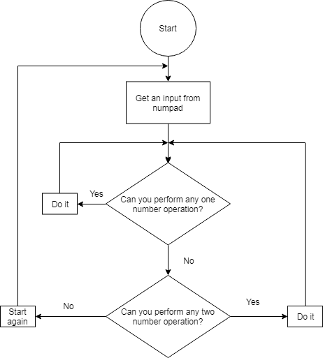
تحتوي الكتلة "دائما" على بيان الحالة الذي يختار العملية اعتمادًا على زر اللوحة. إذا تم الضغط على زر مع الرقم ، فإن هذا الرقم ينتقل إلى الجزء العلوي من المكدس. إذا احتجنا إلى إدخال الرقم الذي يحتوي على أكثر من رقم ، فسيتم ضرب الرقم العلوي في المكدس في 10 وتنتقل هذه القيمة المضروبة إلى أعلى المكدس. إذا تم الضغط على الزر الذي يحتوي على عملية ، يتم تطبيق هذه العملية على أول رقمين في المكدس.
أثناء الاختبار ، وجدنا شيئًا مثيرًا للاهتمام حول الانقسام في Verilog. لسبب غريب إذا حاولنا تقسيم رقمين سالبين ، ستؤدي العملية إلى صفر نتيجة لذلك. لذلك ، من أجل إصلاحه ، كان علينا إضافة فرع لمعالجة هذه الحالة بشكل صريح.
الخلاصة
هذا هو الفيديو الذي يوضح عمل الآلة الحاسبة. أيضا ،
هنا هو جوهر مشروعنا.
زادت دراسة Verilog بشكل كبير من فهمنا لهندسة الكمبيوتر. إلى جانب ذلك ، ساعدنا العمل في فريق على تطوير المهارات الأساسية الأساسية للعمل الجماعي.
المؤلف: Fedoseev Kirill، Yuloskov Artem.