Introduccion
Como estudiantes de primer año de la Universidad de Innopolis, tuvimos la oportunidad de hacer nuestro propio proyecto en arquitectura de computadoras. University nos sugirió varios proyectos y hemos optado por hacer una calculadora basada en pila con notación de pulido inverso. Uno de los requisitos para el proyecto es utilizar el tablero FPGA provisto por la universidad.
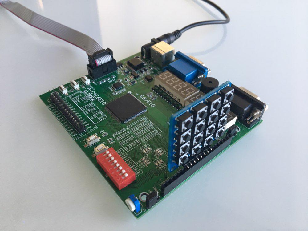
Como nuestra junta, hemos elegido Cyclon IV. Por lo tanto, tuvimos que escribir código en el lenguaje de descripción de hardware. En el curso hemos estudiado Verilog, por lo que lo hemos elegido. Además, la universidad tiene módulos adicionales para FPGA, como el teclado numérico, por lo que decidimos usarlo en nuestro proyecto.
En este artículo, queremos compartir nuestro conocimiento sobre FPGA y Verilog, también le ofrecemos un tutorial para repetir nuestro proyecto.
Diseño básico
Formamos un grupo de dos personas y organizamos nuestra primera reunión. Allí hemos discutido el diseño básico, dividido nuestras responsabilidades y hemos hecho un plan corto con plazos. Esto es lo que se nos ocurre. Necesitamos:
- Implementar pila en el Verilog
- Aprende a trabajar con el teclado numérico
- Implemente la salida a través de la pantalla de 8 segmentos ubicada en la placa FPGA
- Haga un módulo principal que conecte todos los módulos juntos
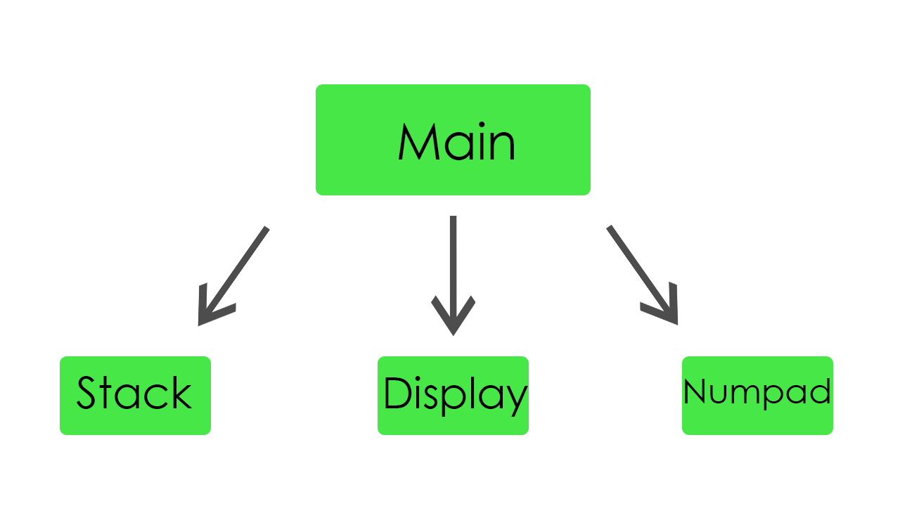
Cada miembro del equipo ha elegido un módulo para escribir. La tarea de primer orden fue implementar pila, salida y entrada. Como se determinó, hemos comenzado a trabajar.
Pila
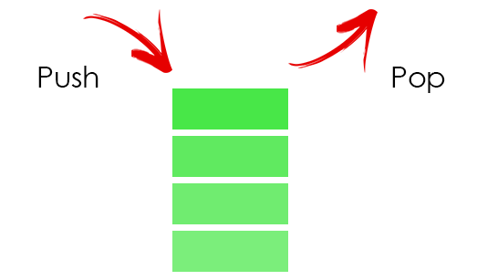
En la pila, almacenamos todos nuestros operandos. Para almacenarlos, dedicamos 32 palabras de memoria.
Código de módulo de pilamodule stack( //Just 50 MHz clock input clock, //Reset signal input reset, //PUSH operation control signal input push, //POP operation control signal input pop, //SWAP operation control signal input swap, //UPDATE operation control signal input write, //Value to write input [31:0] value, //Top element output [31:0] top, //Second element from stack top output [31:0] next, //Total elements count output [5:0] count, //Stack overflow error output error ); //Stack memory for 32 words reg [31:0] memory [0:31]; //Stack pointer on top element, indexing from 0 reg [5:0] pointer = 0; //First element by default is 0 initial memory[0] = 0; //Top stack element assign top = memory[pointer]; //Second element if such exists, 0 otherwise assign next = pointer == 0 ? 0 : memory[pointer - 1]; //Stack elements count assign count = pointer[4:0] + 1; //Stack overflow signal assign error = pointer[5]; always @(posedge clock) begin //Reseting if (reset) begin memory[0] <= 0; pointer <= 0; end //Remove one element form stack if (pop) pointer <= pointer - 1; //Swaps top and next elements if (swap) begin memory[pointer] <= memory[pointer - 1]; memory[pointer - 1] <= memory[pointer]; end //Update top element if (write) memory[pointer - pop] <= value; //Push new zero element on top if (push) begin pointer <= pointer + 1; //Here pointer is still not updated, so +1 memory[pointer + 1] <= 0; end end endmodule
Es solo una pila normal. Si se introduce un nuevo valor, solo aumenta el puntero y coloca este valor en la parte superior de la pila. Si un valor sale de la pila, disminuye el puntero y actualiza el elemento superior.
Para mayor comodidad, agregamos un botón de reinicio para tener la oportunidad de reiniciar nuestro programa durante la ejecución. Además, para la depuración se agregó la oportunidad de detectar el error de desbordamiento de la pila.
Display
En este módulo, implementamos toda la funcionalidad de la pantalla. Es capaz de mostrar dinámicamente los resultados de nuestros cálculos y también los valores de entrada.

Aquí está el código para la pantalla module display_bcd ( //Just 50 MHz clock input clock, //Switching hexademical and decimal representations input show_in_hex, //Asserted if something is going wrong, displaing error message input error, //Value to be displayed in binary format input [31:0] value, //Segments of display output [7:0] control, //LEDs of one segment output [7:0] leds ); // ###0### // # # // # # // 5 1 // # # // # # // ###6### // # # // # # // 4 2 // # # ### // # # #7# // ###3### ### //All representation of used symbols parameter D_0 = 8'b00111111; parameter D_1 = 8'b00000110; parameter D_2 = 8'b01011011; parameter D_3 = 8'b01001111; parameter D_4 = 8'b01100110; parameter D_5 = 8'b01101101; parameter D_6 = 8'b01111101; parameter D_7 = 8'b00000111; parameter D_8 = 8'b01111111; parameter D_9 = 8'b01101111; parameter D_DOT = 8'b10000000; parameter D_A = 8'b01110111; parameter D_B = 8'b01111100; parameter D_C = 8'b01011000; parameter D_D = 8'b01011110; parameter D_E = 8'b01111001; parameter D_F = 8'b01110001; parameter D_R = 8'b01010000; parameter D_O = 8'b01011100; parameter D_MINUS = 8'b01000000; parameter D_EMPTY = 8'b00000000; parameter D_E_CODE = 14; parameter D_R_CODE = 16; parameter D_O_CODE = 17; parameter D_MINUS_CODE = 18; parameter D_EMPTY_CODE = 31; //Delay counter, delaying 8192 clock cycles ~ 0.16 ms reg [12:0] counter = 0; //Saved Binary-Coded Decimal reg [31:0] r_bcd; //Number of segment that is active on current iteration reg [2:0] ctrl = 0; //Current digit shown on the current segment reg [4:0] digit; //Asserted for 1 cycle when conversion to Binary-Coded Decimal is done wire converted; //Intermediate Binary-Coded decimal value wire [31:0] bcd; //Decoded number digits wire [31:0] digits; //Number sign wire sign; //Digits from unsigned numbers wire [31:0] unsigned_number; bcd_convert #(32, 8) bcd_convert( .i_Clock(clock), .i_Binary(unsigned_number), .i_Start(1'b1), .o_BCD(bcd), .o_DV(converted)); //Get number sign assign sign = value[31]; //Get unsigned number assign unsigned_number = sign ? -value : value; //Switching final number representation assign digits = show_in_hex ? unsigned_number : r_bcd; //Constolling segments assign control = ~(1 << ctrl); reg [7:0] r_leds; //Controlling LEDs assign leds = ~r_leds; always @(posedge clock) begin case (digit) 0: r_leds <= D_0; 1: r_leds <= D_1; 2: r_leds <= D_2; 3: r_leds <= D_3; 4: r_leds <= D_4; 5: r_leds <= D_5; 6: r_leds <= D_6; 7: r_leds <= D_7; 8: r_leds <= D_8; 9: r_leds <= D_9; 10: r_leds <= D_A; 11: r_leds <= D_B; 12: r_leds <= D_C; 13: r_leds <= D_D; 14: r_leds <= D_E; 15: r_leds <= D_F; 16: r_leds <= D_R; 17: r_leds <= D_O; 18: r_leds <= D_MINUS; default: r_leds <= D_EMPTY; endcase if (error) //Display error message case(ctrl) 0: digit <= D_R_CODE; 1: digit <= D_O_CODE; 2: digit <= D_R_CODE; 3: digit <= D_R_CODE; 4: digit <= D_E_CODE; 5: digit <= D_EMPTY_CODE; 6: digit <= D_EMPTY_CODE; 7: digit <= D_EMPTY_CODE; endcase else //Select current digit case(ctrl) 0: digit <= digits[3:0]; 1: digit <= digits[31:4] ? digits[7:4] : D_EMPTY_CODE; 2: digit <= digits[31:8] ? digits[11:8] : D_EMPTY_CODE; 3: digit <= digits[31:12] ? digits[15:12] : D_EMPTY_CODE; 4: digit <= digits[31:16] ? digits[19:16] : D_EMPTY_CODE; 5: digit <= digits[31:20] ? digits[23:20] : D_EMPTY_CODE; 6: digit <= digits[31:24] ? digits[27:24] : D_EMPTY_CODE; 7: digit <= sign ? D_MINUS_CODE : (digits[31:28] ? digits[31:28] : D_EMPTY_CODE); endcase //Increase current delay counter <= counter + 1; //Delay is done, increase segment number if (counter == 13'b1000000000000) ctrl <= ctrl + 1; //Save converted Binary-Coded Decimal if (converted) r_bcd <= bcd; end endmodule
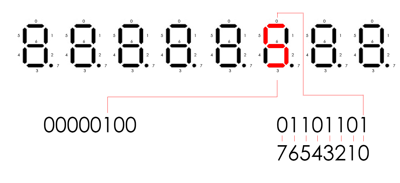
El ciclón IV tiene ocho pantallas de ocho segmentos. Están controlados por 16 pines. Ocho pines controlan segmentos en cada pantalla (llamémoslo led) y otros ocho pines controlan qué pantalla estará activa (solo llámelo control). Por ejemplo, si necesitamos mostrar el dígito 5 en la tercera pantalla, el control debería ser 00000100 y el led debería ser 01101101 (de acuerdo con el esquema en el código). Para mostrar varios dígitos diferentes en diferentes pantallas, necesitamos iluminar periódicamente cada pantalla. Entonces, cada 8192 ciclos de reloj, nos movemos lógicamente a la izquierda en 1 bit nuestra salida de control, que inicialmente es igual a 00000001. Cuando lo movemos, cambiamos el número que se mostrará actualmente. Sucede tan rápido que nuestro ojo no puede ver los cambios, por lo tanto, podemos mostrar diferentes dígitos en cada pantalla.
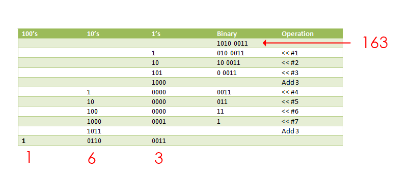
A medida que pasamos al número binario de este módulo, debemos representarlo de alguna manera como dígitos separados. Para este propósito,
encontramos un módulo que lo hace, usando un algoritmo de doble oscilación. Toma como entrada nuestro número binario y lo devuelve como un decimal codificado en binario (4 bits por dígito).
Aquí está el código para ello. module bcd_convert #(parameter INPUT_WIDTH, parameter DECIMAL_DIGITS) ( input i_Clock, input [INPUT_WIDTH-1:0] i_Binary, input i_Start, // output [DECIMAL_DIGITS*4-1:0] o_BCD, output o_DV ); parameter s_IDLE = 3'b000; parameter s_SHIFT = 3'b001; parameter s_CHECK_SHIFT_INDEX = 3'b010; parameter s_ADD = 3'b011; parameter s_CHECK_DIGIT_INDEX = 3'b100; parameter s_BCD_DONE = 3'b101; reg [2:0] r_SM_Main = s_IDLE; // The vector that contains the output BCD reg [DECIMAL_DIGITS*4-1:0] r_BCD = 0; // The vector that contains the input binary value being shifted. reg [INPUT_WIDTH-1:0] r_Binary = 0; // Keeps track of which Decimal Digit we are indexing reg [DECIMAL_DIGITS-1:0] r_Digit_Index = 0; // Keeps track of which loop iteration we are on. // Number of loops performed = INPUT_WIDTH reg [7:0] r_Loop_Count = 0; wire [3:0] w_BCD_Digit; reg r_DV = 1'b0; always @(posedge i_Clock) begin case (r_SM_Main) // Stay in this state until i_Start comes along s_IDLE : begin r_DV <= 1'b0; if (i_Start == 1'b1) begin r_Binary <= i_Binary; r_SM_Main <= s_SHIFT; r_BCD <= 0; end else r_SM_Main <= s_IDLE; end // Always shift the BCD Vector until we have shifted all bits through // Shift the most significant bit of r_Binary into r_BCD lowest bit. s_SHIFT : begin r_BCD <= r_BCD << 1; r_BCD[0] <= r_Binary[INPUT_WIDTH-1]; r_Binary <= r_Binary << 1; r_SM_Main <= s_CHECK_SHIFT_INDEX; end // Check if we are done with shifting in r_Binary vector s_CHECK_SHIFT_INDEX : begin if (r_Loop_Count == INPUT_WIDTH-1) begin r_Loop_Count <= 0; r_SM_Main <= s_BCD_DONE; end else begin r_Loop_Count <= r_Loop_Count + 1; r_SM_Main <= s_ADD; end end // Break down each BCD Digit individually. Check them one-by-one to // see if they are greater than 4. If they are, increment by 3. // Put the result back into r_BCD Vector. s_ADD : begin if (w_BCD_Digit > 4) begin r_BCD[(r_Digit_Index*4)+:4] <= w_BCD_Digit + 3; end r_SM_Main <= s_CHECK_DIGIT_INDEX; end // Check if we are done incrementing all of the BCD Digits s_CHECK_DIGIT_INDEX : begin if (r_Digit_Index == DECIMAL_DIGITS-1) begin r_Digit_Index <= 0; r_SM_Main <= s_SHIFT; end else begin r_Digit_Index <= r_Digit_Index + 1; r_SM_Main <= s_ADD; end end s_BCD_DONE : begin r_DV <= 1'b1; r_SM_Main <= s_IDLE; end default : r_SM_Main <= s_IDLE; endcase end // always @ (posedge i_Clock) assign w_BCD_Digit = r_BCD[r_Digit_Index*4 +: 4]; assign o_BCD = r_BCD; assign o_DV = r_DV; endmodule // Binary_to_BCD
Este módulo funciona con un algoritmo muy interesante. Desplaza todos los bits del número a la izquierda uno por uno y, si los primeros 4 bits son mayores que 4 en decimal, les agrega el decimal 3.
Teclado numérico
Este módulo funciona con el teclado numérico. Lee el valor del teclado numérico y lo pasa al módulo principal. Tenemos dos estados del teclado. Se pueden cambiar presionando uno de los botones en el fpga.
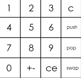
El teclado principal se ve así:
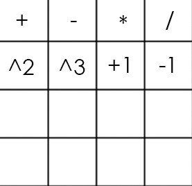
Y la alternativa así:
El código del teclado numérico module numpad ( //Just 50 MHz clock input clock, //Alternative keyboard input alt_key, //Alternative keyboard indicator output alt_led, //Numpad rows input [3:0] rows, //Numpad columns output [3:0] columns, //State change description [5:5] - is_changed, [4:4] - keyboard, [3:0] - button output [5:0] value ); // col 0 col 1 col 2 col 3 // // ############################# // # # # # # // # 1(0) # 2(4) # 3(8) # A(12)# row 0 // # # # # # // ############################# // # # # # # // # 4(1) # 5(5) # 6(9) # B(13)# row 1 // # # # # # // ############################# // # # # # # // # 7(2) # 8(6) # 9(10)# C(14)# row 2 // # # # # # // ############################# // # # # # # // # 0(3) # F(7) # E(11)# D(15)# row 3 // # # # # # // ############################# parameter BTN_EMPTY = 6'b000000; //Previous pressed button reg [5:0] prev = 0; //Current pressed button reg [5:0] cur = 0; //Current column number reg [1:0] col = 0; //Counter for delay reg [8:0] counter = 0; //Rows pressed flags reg [3:0] pressed = 0; //Is alternative keyboard reg is_alt = 0; //Alt key on prev clock cycle reg prev_alt_key = 0; //Controlling column assign columns = ~(1 << col); assign alt_led = ~is_alt; always @(posedge clock) begin //Increase counter counter <= counter + 1; //Evaluating alternative keyboard signal if (value != BTN_EMPTY) is_alt <= 0; else is_alt <= (alt_key == 1 && prev_alt_key == 0) ? ~is_alt : is_alt; prev_alt_key <= alt_key; if (counter == 9'b1111111111) begin //Evaluating current button case(~rows) 4'b0001: begin pressed[col] <= 1; cur <= {1'b1, ~is_alt, col, 2'b00}; end 4'b0010: begin pressed[col] <= 1; cur <= {1'b1, ~is_alt, col, 2'b01}; end 4'b0100: begin pressed[col] <= 1; cur <= {1'b1, ~is_alt, col, 2'b10}; end 4'b1000: begin pressed[col] <= 1; cur <= {1'b1, ~is_alt, col, 2'b11}; end default: begin pressed[col] <= 0; cur <= pressed ? cur : BTN_EMPTY; end endcase end //increase column number when counter is 9'011111111, using different edges of counter[8] to let counter pass through zero, to assert wire value if need if (counter == 9'b011111111) begin //Saving previous button every 4 iterations if (&col) prev <= cur; col <= col + 1; end end //Evaluating state change //Comparing current and previous states without keyboard bit assign value = (counter == 9'b000000000 && col == 2'b11 && {prev[5], prev[3:0]} != {cur[5], cur[3:0]}) ? cur : BTN_EMPTY; endmodule
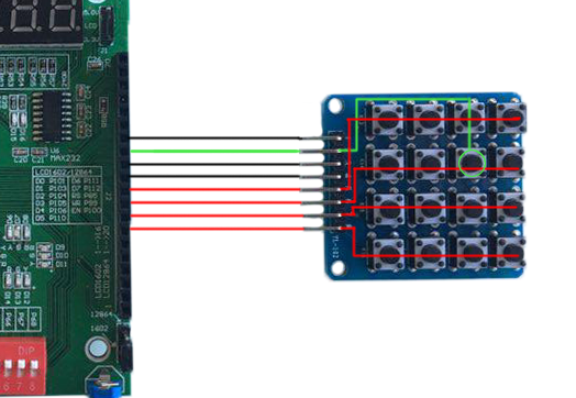
Entonces, el teclado numérico es un esquema que contiene 16 botones (4 filas y 4 columnas). Para obtener el número del botón que se presionó, necesitamos 4 salidas (sean columnas) y 4 entradas (filas). Pasamos el voltaje a cada columna periódicamente y si se presiona el botón, el circuito se cierra y cierta fila se vuelve verdadera como entrada. La combinación del número de la columna y el número de la fila determina de forma exclusiva nuestro botón.
Si usamos el teclado principal en el ejemplo anterior, obtendremos el número 5 como entrada.
Módulo principal
El módulo principal conecta todas las partes y realmente hace cálculos.
El módulo principal aquí module main( //Just 50 MHz clock input clock, //Reset signal input reset, //Representation switch input show_in_hex, //Show stack elements count switch input show_count, //Button, switches to operations keyboard input alt_numpad_key, //Alternative keyboard indicator output alt_numpad_led, //Numpad rows and columns input [3:0] numpad_rows, output [3:0] numpad_columns, //Display and display control output [7:0] display_leds, output [7:0] display_control ); // 1 2 3 C // 4 5 6 PUSH // 7 8 9 POP // 0 +- CE SWAP parameter BTN_0 = 6'b110011; parameter BTN_1 = 6'b110000; parameter BTN_2 = 6'b110100; parameter BTN_3 = 6'b111000; parameter BTN_4 = 6'b110001; parameter BTN_5 = 6'b110101; parameter BTN_6 = 6'b111001; parameter BTN_7 = 6'b110010; parameter BTN_8 = 6'b110110; parameter BTN_9 = 6'b111010; parameter BTN_CLEAR_DIGIT = 6'b111100; parameter BTN_PUSH = 6'b111101; parameter BTN_POP = 6'b111110; parameter BTN_SWAP = 6'b111111; parameter BTN_CLEAR_NUMBER = 6'b111011; parameter BTN_UNARY_MINUS = 6'b110111; // + - * / // sqr cbe inc dec parameter BTN_ADDITION = 6'b100000; parameter BTN_SUBTRACTION = 6'b100100; parameter BTN_MULTIPLICATION = 6'b101000; parameter BTN_DIVISION = 6'b101100; parameter BTN_SQUARE = 6'b100001; parameter BTN_CUBE = 6'b100101; parameter BTN_INCREMENT = 6'b101001; parameter BTN_DECREMENT = 6'b101101; //Numpad state wire [5:0] pressed; //Stack elements count wire [5:0] count; //First and second stack elements wire [31:0] top, next; wire stack_error; //Evaluated new value reg [31:0] new_value; //Stack control signals reg write, push, pop, swap; reg arithmetic_error = 0; numpad numpad( .clock (clock), .alt_key (~alt_numpad_key), .alt_led (alt_numpad_led), .rows (numpad_rows), .columns (numpad_columns), .value (pressed) ); stack stack( .clock (clock), .reset (~reset), .push (push), .pop (pop), .swap (swap), .write (write), .value (new_value), .top (top), .next (next), .count (count), .error (stack_error) ); display_bcd display( .clock (clock), .error (stack_error || arithmetic_error), .show_in_hex (show_in_hex), .value (show_count ? count : top), .control (display_control), .leds (display_leds) ); // Division result wire [31:0] res; assign res = ((next[31] ? -next : next) / (top[31] ? -top : top)); always @(posedge clock) begin //Reseting arithmetic error if (~reset) arithmetic_error <= 0; case (pressed) BTN_0: begin write <= 1; new_value <= top * 10; end BTN_1: begin write <= 1; new_value <= top * 10 + (top[31] ? -1 : 1); end BTN_2: begin write <= 1; new_value <= top * 10 + (top[31] ? -2 : 2); end BTN_3: begin write <= 1; new_value <= top * 10 + (top[31] ? -3 : 3); end BTN_4: begin write <= 1; new_value <= top * 10 + (top[31] ? -4 : 4); end BTN_5: begin write <= 1; new_value <= top * 10 + (top[31] ? -5 : 5); end BTN_6: begin write <= 1; new_value <= top * 10 + (top[31] ? -6 : 6); end BTN_7: begin write <= 1; new_value <= top * 10 + (top[31] ? -7 : 7); end BTN_8: begin write <= 1; new_value <= top * 10 + (top[31] ? -8 : 8); end BTN_9: begin write <= 1; new_value <= top * 10 + (top[31] ? -9 : 9); end BTN_CLEAR_DIGIT: begin write <= 1; new_value <= top / 10; end BTN_CLEAR_NUMBER: begin write <= 1; new_value <= 0; end BTN_PUSH: begin push <= 1; end BTN_POP: begin pop <= 1; end BTN_SWAP: begin swap <= 1; end BTN_UNARY_MINUS: begin write <= 1; new_value <= -top; end BTN_ADDITION: begin pop <= 1; write <= 1; new_value <= next + top; end BTN_SUBTRACTION: begin pop <= 1; write <= 1; new_value <= next - top; end BTN_MULTIPLICATION: begin pop <= 1; write <= 1; new_value <= next * top; end BTN_DIVISION: begin pop <= 1; write <= 1; new_value <= (next[31] ^ top[31] ? -res : res); arithmetic_error <= ~(|top); end BTN_SQUARE: begin write <= 1; new_value <= top * top; end BTN_CUBE: begin write <= 1; new_value <= top * top * top; end BTN_INCREMENT: begin write <= 1; new_value <= top + 1; end BTN_DECREMENT: begin write <= 1; new_value <= top - 1; end default: // Nothing usefull is pressed begin write <= 0; push <= 0; pop <= 0; swap <= 0; end endcase end endmodule
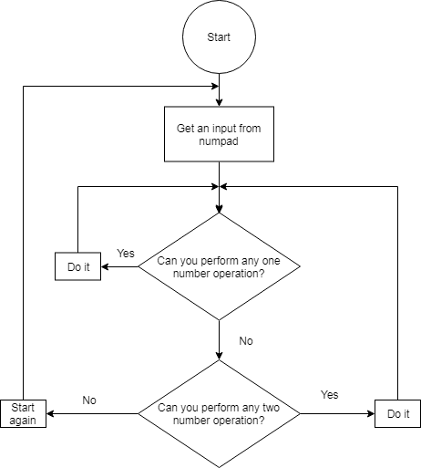
El bloque "siempre" contiene una declaración de caso que elige la operación según el botón del teclado numérico que se presiona. Si un botón con el dígito presionado, este dígito va a la parte superior de la pila. Si necesitamos ingresar el número que tiene más de un dígito, entonces el número superior en la pila se multiplica por 10 y este valor multiplicado va a la parte superior de la pila. Si se presiona el botón con una operación, esta operación se aplica a los primeros dos números en la pila.
Durante las pruebas, encontramos algo interesante sobre la división en Verilog. Por alguna extraña razón, si intentamos dividir dos números negativos, la operación producirá un cero como resultado. Entonces, para solucionarlo, tuvimos que agregar una rama para procesar este caso explícitamente.
Conclusión
Aquí está el video, que demuestra el trabajo de la calculadora. Además,
aquí está el github de nuestro proyecto.
Estudiar Verilog aumentó drásticamente nuestra comprensión de la arquitectura de la computadora. Además, trabajar en equipo nos ha ayudado a desarrollar habilidades básicas para el trabajo en equipo.
Autores: Fedoseev Kirill, Yuloskov Artem.