Pendahuluan
Sebagai mahasiswa tahun pertama dari Innopolis University, kami memiliki kesempatan untuk membuat proyek kami sendiri dalam arsitektur komputer. Universitas menyarankan kami beberapa proyek dan kami telah memilih untuk membuat kalkulator berbasis tumpukan dengan notasi polish terbalik. Salah satu persyaratan untuk proyek ini adalah menggunakan papan FPGA yang disediakan oleh universitas.
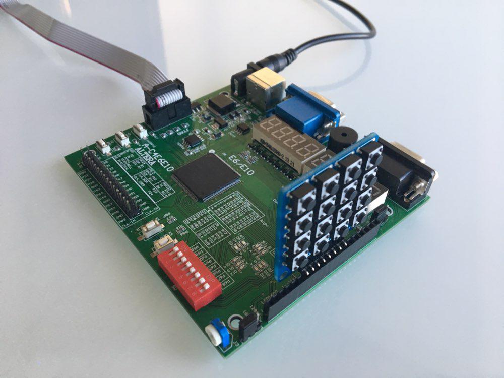
Sebagai dewan kami, kami telah memilih Cyclon IV. Oleh karena itu, kami harus menulis kode pada bahasa deskripsi perangkat keras. Dalam kursus kami telah mempelajari Verilog, jadi kami telah memilihnya. Selain itu, universitas memiliki modul tambahan untuk FPGA, seperti numpad, sehingga kami memutuskan untuk menggunakannya dalam proyek kami.
Dalam artikel ini, kami ingin berbagi pengetahuan kami tentang FPGA dan Verilog, juga memberi Anda tutorial untuk mengulangi proyek kami.
Desain dasar
Kami membentuk sekelompok dua orang dan mengatur pertemuan pertama kami. Di sana kami telah membahas desain dasar, membagi tanggung jawab kami dan telah membuat rencana pendek dengan tenggat waktu. Inilah yang kami temukan. Kita perlu:
- Menerapkan tumpukan di Verilog
- Pelajari cara bekerja dengan numpad
- Terapkan output melalui tampilan 8-segmen yang terletak di papan FPGA
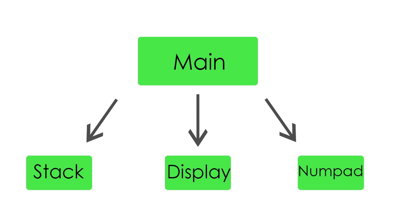
- Buat modul utama yang akan menghubungkan semua modul bersama
Setiap anggota tim telah memilih sendiri modul untuk ditulis. Tugas orde pertama adalah mengimplementasikan stack, output, dan input. Seperti yang ditentukan, kami sudah mulai bekerja.
Tumpukan
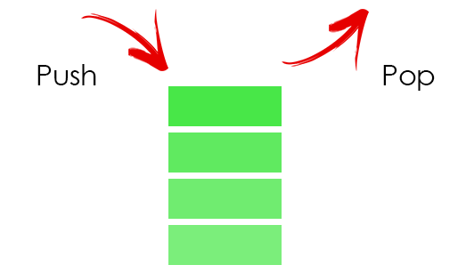
Dalam tumpukan, kami menyimpan semua operan kami. Untuk menyimpannya, kami mencurahkan 32 kata memori.
Tumpuk kode modulmodule stack( //Just 50 MHz clock input clock, //Reset signal input reset, //PUSH operation control signal input push, //POP operation control signal input pop, //SWAP operation control signal input swap, //UPDATE operation control signal input write, //Value to write input [31:0] value, //Top element output [31:0] top, //Second element from stack top output [31:0] next, //Total elements count output [5:0] count, //Stack overflow error output error ); //Stack memory for 32 words reg [31:0] memory [0:31]; //Stack pointer on top element, indexing from 0 reg [5:0] pointer = 0; //First element by default is 0 initial memory[0] = 0; //Top stack element assign top = memory[pointer]; //Second element if such exists, 0 otherwise assign next = pointer == 0 ? 0 : memory[pointer - 1]; //Stack elements count assign count = pointer[4:0] + 1; //Stack overflow signal assign error = pointer[5]; always @(posedge clock) begin //Reseting if (reset) begin memory[0] <= 0; pointer <= 0; end //Remove one element form stack if (pop) pointer <= pointer - 1; //Swaps top and next elements if (swap) begin memory[pointer] <= memory[pointer - 1]; memory[pointer - 1] <= memory[pointer]; end //Update top element if (write) memory[pointer - pop] <= value; //Push new zero element on top if (push) begin pointer <= pointer + 1; //Here pointer is still not updated, so +1 memory[pointer + 1] <= 0; end end endmodule
Itu hanya tumpukan biasa. Jika nilai baru didorong ke sana, itu hanya meningkatkan pointer dan menempatkan nilai ini di atas tumpukan. Jika nilai muncul dari tumpukan itu mengurangi pointer dan memperbarui elemen teratas.
Untuk kenyamanan, kami menambahkan tombol reset, agar memiliki kesempatan untuk memulai kembali program kami saat eksekusi. Juga, untuk debugging ditambahkan kesempatan untuk menangkap kesalahan stack overflow.
Tampilan
Dalam modul ini, kami menerapkan semua fungsi layar. Itu mampu secara dinamis menunjukkan hasil perhitungan kami dan juga nilai input.

Ini adalah kode untuk tampilan module display_bcd ( //Just 50 MHz clock input clock, //Switching hexademical and decimal representations input show_in_hex, //Asserted if something is going wrong, displaing error message input error, //Value to be displayed in binary format input [31:0] value, //Segments of display output [7:0] control, //LEDs of one segment output [7:0] leds ); // ###0### // # # // # # // 5 1 // # # // # # // ###6### // # # // # # // 4 2 // # # ### // # # #7# // ###3### ### //All representation of used symbols parameter D_0 = 8'b00111111; parameter D_1 = 8'b00000110; parameter D_2 = 8'b01011011; parameter D_3 = 8'b01001111; parameter D_4 = 8'b01100110; parameter D_5 = 8'b01101101; parameter D_6 = 8'b01111101; parameter D_7 = 8'b00000111; parameter D_8 = 8'b01111111; parameter D_9 = 8'b01101111; parameter D_DOT = 8'b10000000; parameter D_A = 8'b01110111; parameter D_B = 8'b01111100; parameter D_C = 8'b01011000; parameter D_D = 8'b01011110; parameter D_E = 8'b01111001; parameter D_F = 8'b01110001; parameter D_R = 8'b01010000; parameter D_O = 8'b01011100; parameter D_MINUS = 8'b01000000; parameter D_EMPTY = 8'b00000000; parameter D_E_CODE = 14; parameter D_R_CODE = 16; parameter D_O_CODE = 17; parameter D_MINUS_CODE = 18; parameter D_EMPTY_CODE = 31; //Delay counter, delaying 8192 clock cycles ~ 0.16 ms reg [12:0] counter = 0; //Saved Binary-Coded Decimal reg [31:0] r_bcd; //Number of segment that is active on current iteration reg [2:0] ctrl = 0; //Current digit shown on the current segment reg [4:0] digit; //Asserted for 1 cycle when conversion to Binary-Coded Decimal is done wire converted; //Intermediate Binary-Coded decimal value wire [31:0] bcd; //Decoded number digits wire [31:0] digits; //Number sign wire sign; //Digits from unsigned numbers wire [31:0] unsigned_number; bcd_convert #(32, 8) bcd_convert( .i_Clock(clock), .i_Binary(unsigned_number), .i_Start(1'b1), .o_BCD(bcd), .o_DV(converted)); //Get number sign assign sign = value[31]; //Get unsigned number assign unsigned_number = sign ? -value : value; //Switching final number representation assign digits = show_in_hex ? unsigned_number : r_bcd; //Constolling segments assign control = ~(1 << ctrl); reg [7:0] r_leds; //Controlling LEDs assign leds = ~r_leds; always @(posedge clock) begin case (digit) 0: r_leds <= D_0; 1: r_leds <= D_1; 2: r_leds <= D_2; 3: r_leds <= D_3; 4: r_leds <= D_4; 5: r_leds <= D_5; 6: r_leds <= D_6; 7: r_leds <= D_7; 8: r_leds <= D_8; 9: r_leds <= D_9; 10: r_leds <= D_A; 11: r_leds <= D_B; 12: r_leds <= D_C; 13: r_leds <= D_D; 14: r_leds <= D_E; 15: r_leds <= D_F; 16: r_leds <= D_R; 17: r_leds <= D_O; 18: r_leds <= D_MINUS; default: r_leds <= D_EMPTY; endcase if (error) //Display error message case(ctrl) 0: digit <= D_R_CODE; 1: digit <= D_O_CODE; 2: digit <= D_R_CODE; 3: digit <= D_R_CODE; 4: digit <= D_E_CODE; 5: digit <= D_EMPTY_CODE; 6: digit <= D_EMPTY_CODE; 7: digit <= D_EMPTY_CODE; endcase else //Select current digit case(ctrl) 0: digit <= digits[3:0]; 1: digit <= digits[31:4] ? digits[7:4] : D_EMPTY_CODE; 2: digit <= digits[31:8] ? digits[11:8] : D_EMPTY_CODE; 3: digit <= digits[31:12] ? digits[15:12] : D_EMPTY_CODE; 4: digit <= digits[31:16] ? digits[19:16] : D_EMPTY_CODE; 5: digit <= digits[31:20] ? digits[23:20] : D_EMPTY_CODE; 6: digit <= digits[31:24] ? digits[27:24] : D_EMPTY_CODE; 7: digit <= sign ? D_MINUS_CODE : (digits[31:28] ? digits[31:28] : D_EMPTY_CODE); endcase //Increase current delay counter <= counter + 1; //Delay is done, increase segment number if (counter == 13'b1000000000000) ctrl <= ctrl + 1; //Save converted Binary-Coded Decimal if (converted) r_bcd <= bcd; end endmodule
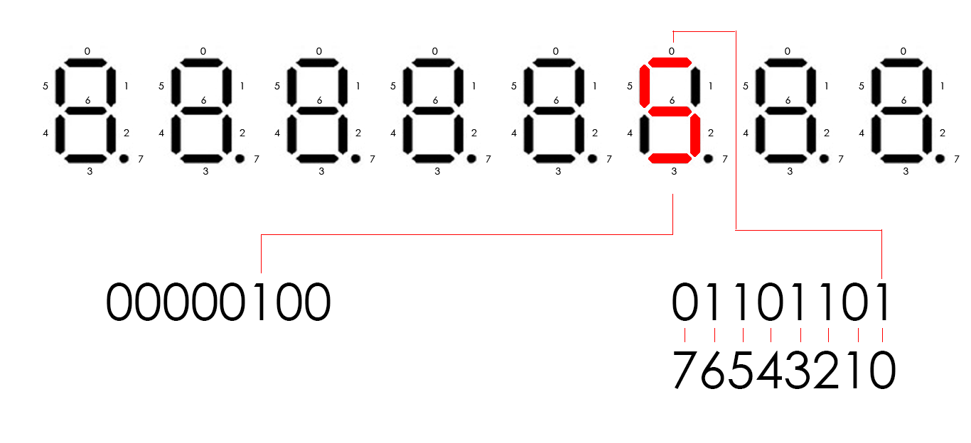
Topan IV memiliki delapan layar delapan segmen. Mereka dikendalikan oleh 16 pin. Delapan pin mengontrol segmen di setiap tampilan (sebut saja dipimpin) dan delapan pin lainnya mengontrol tampilan mana yang akan aktif (sebut saja kontrol). Misalnya, jika kita perlu menunjukkan angka 5 pada tampilan ketiga, kontrol harus 00000100 dan led harus 01101101 (sesuai dengan skema dalam kode). Untuk menampilkan beberapa digit berbeda pada tampilan berbeda, kita perlu menyalakan setiap tampilan secara berkala. Jadi, setiap siklus 8192 clock, kami bergerak ke kiri secara logis dengan 1 bit output kontrol kami, yang awalnya sama dengan 00000001. Ketika kami memindahkannya, kami mengubah angka yang akan ditampilkan saat ini. Ini terjadi begitu cepat, sehingga mata kita tidak dapat melihat perubahan, sehingga, kita dapat menunjukkan angka yang berbeda di setiap layar.
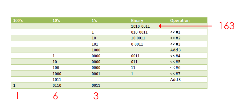
Ketika kita meneruskan ke nomor biner modul ini, kita perlu menggambarkannya sebagai digit terpisah. Untuk tujuan ini, kami
menemukan modul yang membuatnya, menggunakan algoritma dabble ganda. Dibutuhkan sebagai input nomor biner kami dan mengembalikannya sebagai desimal berkode biner (4 bit per digit).
Ini kode untuk itu module bcd_convert #(parameter INPUT_WIDTH, parameter DECIMAL_DIGITS) ( input i_Clock, input [INPUT_WIDTH-1:0] i_Binary, input i_Start, // output [DECIMAL_DIGITS*4-1:0] o_BCD, output o_DV ); parameter s_IDLE = 3'b000; parameter s_SHIFT = 3'b001; parameter s_CHECK_SHIFT_INDEX = 3'b010; parameter s_ADD = 3'b011; parameter s_CHECK_DIGIT_INDEX = 3'b100; parameter s_BCD_DONE = 3'b101; reg [2:0] r_SM_Main = s_IDLE; // The vector that contains the output BCD reg [DECIMAL_DIGITS*4-1:0] r_BCD = 0; // The vector that contains the input binary value being shifted. reg [INPUT_WIDTH-1:0] r_Binary = 0; // Keeps track of which Decimal Digit we are indexing reg [DECIMAL_DIGITS-1:0] r_Digit_Index = 0; // Keeps track of which loop iteration we are on. // Number of loops performed = INPUT_WIDTH reg [7:0] r_Loop_Count = 0; wire [3:0] w_BCD_Digit; reg r_DV = 1'b0; always @(posedge i_Clock) begin case (r_SM_Main) // Stay in this state until i_Start comes along s_IDLE : begin r_DV <= 1'b0; if (i_Start == 1'b1) begin r_Binary <= i_Binary; r_SM_Main <= s_SHIFT; r_BCD <= 0; end else r_SM_Main <= s_IDLE; end // Always shift the BCD Vector until we have shifted all bits through // Shift the most significant bit of r_Binary into r_BCD lowest bit. s_SHIFT : begin r_BCD <= r_BCD << 1; r_BCD[0] <= r_Binary[INPUT_WIDTH-1]; r_Binary <= r_Binary << 1; r_SM_Main <= s_CHECK_SHIFT_INDEX; end // Check if we are done with shifting in r_Binary vector s_CHECK_SHIFT_INDEX : begin if (r_Loop_Count == INPUT_WIDTH-1) begin r_Loop_Count <= 0; r_SM_Main <= s_BCD_DONE; end else begin r_Loop_Count <= r_Loop_Count + 1; r_SM_Main <= s_ADD; end end // Break down each BCD Digit individually. Check them one-by-one to // see if they are greater than 4. If they are, increment by 3. // Put the result back into r_BCD Vector. s_ADD : begin if (w_BCD_Digit > 4) begin r_BCD[(r_Digit_Index*4)+:4] <= w_BCD_Digit + 3; end r_SM_Main <= s_CHECK_DIGIT_INDEX; end // Check if we are done incrementing all of the BCD Digits s_CHECK_DIGIT_INDEX : begin if (r_Digit_Index == DECIMAL_DIGITS-1) begin r_Digit_Index <= 0; r_SM_Main <= s_SHIFT; end else begin r_Digit_Index <= r_Digit_Index + 1; r_SM_Main <= s_ADD; end end s_BCD_DONE : begin r_DV <= 1'b1; r_SM_Main <= s_IDLE; end default : r_SM_Main <= s_IDLE; endcase end // always @ (posedge i_Clock) assign w_BCD_Digit = r_BCD[r_Digit_Index*4 +: 4]; assign o_BCD = r_BCD; assign o_DV = r_DV; endmodule // Binary_to_BCD
Modul ini bekerja dengan algoritma yang sangat menarik. Ini menggeser semua bit dalam angka ke kiri satu-per-satu dan, jika 4 bit pertama lebih besar dari 4 dalam desimal, itu menambah desimal 3 untuk mereka.
Numpad
Modul ini bekerja dengan numpad. Bunyinya nilai dari numbpad dan meneruskannya ke modul utama. Kami memiliki dua status keyboard. Mereka dapat diaktifkan dengan menekan salah satu tombol pada FPGA.
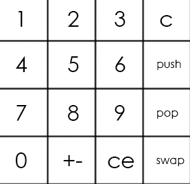
Keyboard utama terlihat seperti itu:
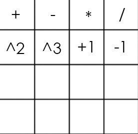
Dan alternatifnya seperti itu:
Kode numpad module numpad ( //Just 50 MHz clock input clock, //Alternative keyboard input alt_key, //Alternative keyboard indicator output alt_led, //Numpad rows input [3:0] rows, //Numpad columns output [3:0] columns, //State change description [5:5] - is_changed, [4:4] - keyboard, [3:0] - button output [5:0] value ); // col 0 col 1 col 2 col 3 // // ############################# // # # # # # // # 1(0) # 2(4) # 3(8) # A(12)# row 0 // # # # # # // ############################# // # # # # # // # 4(1) # 5(5) # 6(9) # B(13)# row 1 // # # # # # // ############################# // # # # # # // # 7(2) # 8(6) # 9(10)# C(14)# row 2 // # # # # # // ############################# // # # # # # // # 0(3) # F(7) # E(11)# D(15)# row 3 // # # # # # // ############################# parameter BTN_EMPTY = 6'b000000; //Previous pressed button reg [5:0] prev = 0; //Current pressed button reg [5:0] cur = 0; //Current column number reg [1:0] col = 0; //Counter for delay reg [8:0] counter = 0; //Rows pressed flags reg [3:0] pressed = 0; //Is alternative keyboard reg is_alt = 0; //Alt key on prev clock cycle reg prev_alt_key = 0; //Controlling column assign columns = ~(1 << col); assign alt_led = ~is_alt; always @(posedge clock) begin //Increase counter counter <= counter + 1; //Evaluating alternative keyboard signal if (value != BTN_EMPTY) is_alt <= 0; else is_alt <= (alt_key == 1 && prev_alt_key == 0) ? ~is_alt : is_alt; prev_alt_key <= alt_key; if (counter == 9'b1111111111) begin //Evaluating current button case(~rows) 4'b0001: begin pressed[col] <= 1; cur <= {1'b1, ~is_alt, col, 2'b00}; end 4'b0010: begin pressed[col] <= 1; cur <= {1'b1, ~is_alt, col, 2'b01}; end 4'b0100: begin pressed[col] <= 1; cur <= {1'b1, ~is_alt, col, 2'b10}; end 4'b1000: begin pressed[col] <= 1; cur <= {1'b1, ~is_alt, col, 2'b11}; end default: begin pressed[col] <= 0; cur <= pressed ? cur : BTN_EMPTY; end endcase end //increase column number when counter is 9'011111111, using different edges of counter[8] to let counter pass through zero, to assert wire value if need if (counter == 9'b011111111) begin //Saving previous button every 4 iterations if (&col) prev <= cur; col <= col + 1; end end //Evaluating state change //Comparing current and previous states without keyboard bit assign value = (counter == 9'b000000000 && col == 2'b11 && {prev[5], prev[3:0]} != {cur[5], cur[3:0]}) ? cur : BTN_EMPTY; endmodule
Jadi, numpad adalah skema yang berisi 16 tombol (4 baris dan 4 kolom). Untuk mendapatkan jumlah tombol yang ditekan kita perlu 4 output (biarlah kolom) dan 4 input (baris). Kami melewatkan tegangan ke setiap kolom secara berkala dan jika tombol ditekan, sirkuit ditutup dan baris tertentu menjadi benar sebagai input. Kombinasi jumlah kolom dan jumlah baris secara unik menentukan tombol kami.
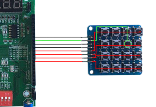
Jika kita menggunakan keyboard utama pada contoh di atas, kita akan mendapatkan nomor 5 sebagai input.
Modul utama
Modul utama menghubungkan semua bagian bersama-sama dan benar-benar membuat perhitungan.
Modul utama di sini module main( //Just 50 MHz clock input clock, //Reset signal input reset, //Representation switch input show_in_hex, //Show stack elements count switch input show_count, //Button, switches to operations keyboard input alt_numpad_key, //Alternative keyboard indicator output alt_numpad_led, //Numpad rows and columns input [3:0] numpad_rows, output [3:0] numpad_columns, //Display and display control output [7:0] display_leds, output [7:0] display_control ); // 1 2 3 C // 4 5 6 PUSH // 7 8 9 POP // 0 +- CE SWAP parameter BTN_0 = 6'b110011; parameter BTN_1 = 6'b110000; parameter BTN_2 = 6'b110100; parameter BTN_3 = 6'b111000; parameter BTN_4 = 6'b110001; parameter BTN_5 = 6'b110101; parameter BTN_6 = 6'b111001; parameter BTN_7 = 6'b110010; parameter BTN_8 = 6'b110110; parameter BTN_9 = 6'b111010; parameter BTN_CLEAR_DIGIT = 6'b111100; parameter BTN_PUSH = 6'b111101; parameter BTN_POP = 6'b111110; parameter BTN_SWAP = 6'b111111; parameter BTN_CLEAR_NUMBER = 6'b111011; parameter BTN_UNARY_MINUS = 6'b110111; // + - * / // sqr cbe inc dec parameter BTN_ADDITION = 6'b100000; parameter BTN_SUBTRACTION = 6'b100100; parameter BTN_MULTIPLICATION = 6'b101000; parameter BTN_DIVISION = 6'b101100; parameter BTN_SQUARE = 6'b100001; parameter BTN_CUBE = 6'b100101; parameter BTN_INCREMENT = 6'b101001; parameter BTN_DECREMENT = 6'b101101; //Numpad state wire [5:0] pressed; //Stack elements count wire [5:0] count; //First and second stack elements wire [31:0] top, next; wire stack_error; //Evaluated new value reg [31:0] new_value; //Stack control signals reg write, push, pop, swap; reg arithmetic_error = 0; numpad numpad( .clock (clock), .alt_key (~alt_numpad_key), .alt_led (alt_numpad_led), .rows (numpad_rows), .columns (numpad_columns), .value (pressed) ); stack stack( .clock (clock), .reset (~reset), .push (push), .pop (pop), .swap (swap), .write (write), .value (new_value), .top (top), .next (next), .count (count), .error (stack_error) ); display_bcd display( .clock (clock), .error (stack_error || arithmetic_error), .show_in_hex (show_in_hex), .value (show_count ? count : top), .control (display_control), .leds (display_leds) ); // Division result wire [31:0] res; assign res = ((next[31] ? -next : next) / (top[31] ? -top : top)); always @(posedge clock) begin //Reseting arithmetic error if (~reset) arithmetic_error <= 0; case (pressed) BTN_0: begin write <= 1; new_value <= top * 10; end BTN_1: begin write <= 1; new_value <= top * 10 + (top[31] ? -1 : 1); end BTN_2: begin write <= 1; new_value <= top * 10 + (top[31] ? -2 : 2); end BTN_3: begin write <= 1; new_value <= top * 10 + (top[31] ? -3 : 3); end BTN_4: begin write <= 1; new_value <= top * 10 + (top[31] ? -4 : 4); end BTN_5: begin write <= 1; new_value <= top * 10 + (top[31] ? -5 : 5); end BTN_6: begin write <= 1; new_value <= top * 10 + (top[31] ? -6 : 6); end BTN_7: begin write <= 1; new_value <= top * 10 + (top[31] ? -7 : 7); end BTN_8: begin write <= 1; new_value <= top * 10 + (top[31] ? -8 : 8); end BTN_9: begin write <= 1; new_value <= top * 10 + (top[31] ? -9 : 9); end BTN_CLEAR_DIGIT: begin write <= 1; new_value <= top / 10; end BTN_CLEAR_NUMBER: begin write <= 1; new_value <= 0; end BTN_PUSH: begin push <= 1; end BTN_POP: begin pop <= 1; end BTN_SWAP: begin swap <= 1; end BTN_UNARY_MINUS: begin write <= 1; new_value <= -top; end BTN_ADDITION: begin pop <= 1; write <= 1; new_value <= next + top; end BTN_SUBTRACTION: begin pop <= 1; write <= 1; new_value <= next - top; end BTN_MULTIPLICATION: begin pop <= 1; write <= 1; new_value <= next * top; end BTN_DIVISION: begin pop <= 1; write <= 1; new_value <= (next[31] ^ top[31] ? -res : res); arithmetic_error <= ~(|top); end BTN_SQUARE: begin write <= 1; new_value <= top * top; end BTN_CUBE: begin write <= 1; new_value <= top * top * top; end BTN_INCREMENT: begin write <= 1; new_value <= top + 1; end BTN_DECREMENT: begin write <= 1; new_value <= top - 1; end default: // Nothing usefull is pressed begin write <= 0; push <= 0; pop <= 0; swap <= 0; end endcase end endmodule
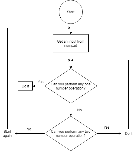
Blok "selalu" berisi pernyataan kasus yang memilih operasi tergantung pada tombol numpad yang ditekan. Jika tombol dengan digit ditekan, maka digit ini menuju ke bagian atas tumpukan. Jika kita perlu memasukkan angka yang memiliki lebih dari satu digit, maka angka teratas dalam tumpukan dikalikan dengan 10 dan nilai yang dikalikan ini menuju ke bagian atas tumpukan. Jika tombol dengan operasi ditekan, operasi ini berlaku untuk dua angka pertama dalam tumpukan.
Selama pengujian, kami menemukan hal yang menarik tentang pembagian di Verilog. Untuk beberapa alasan aneh jika kita akan mencoba membagi dua angka negatif, hasilnya akan menghasilkan nol. Jadi, untuk memperbaikinya, kami harus menambahkan cabang untuk memproses kasus ini secara eksplisit.
Kesimpulan
Ini adalah videonya, yang menunjukkan kerja kalkulator. Juga,
inilah github dari proyek kami.
Mempelajari Verilog secara drastis meningkatkan pemahaman kita tentang arsitektur komputer. Selain itu, bekerja dalam tim telah membantu kami mengembangkan soft skill dasar untuk kerja tim.
Penulis: Fedoseev Kirill, Yuloskov Artem.