1. Introdução
Como alunos do primeiro ano da Universidade de Innopolis, tivemos a oportunidade de fazer nosso próprio projeto em arquitetura de computadores. A Universidade nos sugeriu vários projetos e optamos por fazer uma calculadora baseada em pilha com notação de polimento reverso. Um dos requisitos para o projeto é usar a placa FPGA fornecida pela universidade.
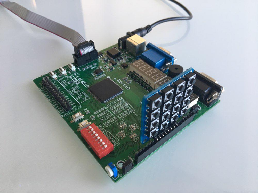
Como nosso conselho, escolhemos o Cyclon IV. Portanto, tivemos que escrever código na linguagem de descrição de hardware. No curso, estudamos o Verilog, por isso escolhemos. Além disso, a universidade possui módulos adicionais para FPGA, como o numpad, por isso decidimos usá-lo em nosso projeto.
Neste artigo, queremos compartilhar nosso conhecimento sobre FPGA e Verilog, além de fornecer um tutorial para repetir nosso projeto.
Projeto básico
Formamos um grupo de duas pessoas e organizamos nosso primeiro encontro. Lá, discutimos o projeto básico, dividimos nossas responsabilidades e fizemos um plano curto com prazos. Isto é o que criamos. Precisamos:
- Implementar pilha no Verilog
- Aprenda a trabalhar com o numpad
- Implemente a saída através da tela de 8 segmentos localizada na placa FPGA
- Faça um módulo principal que conecte todos os módulos
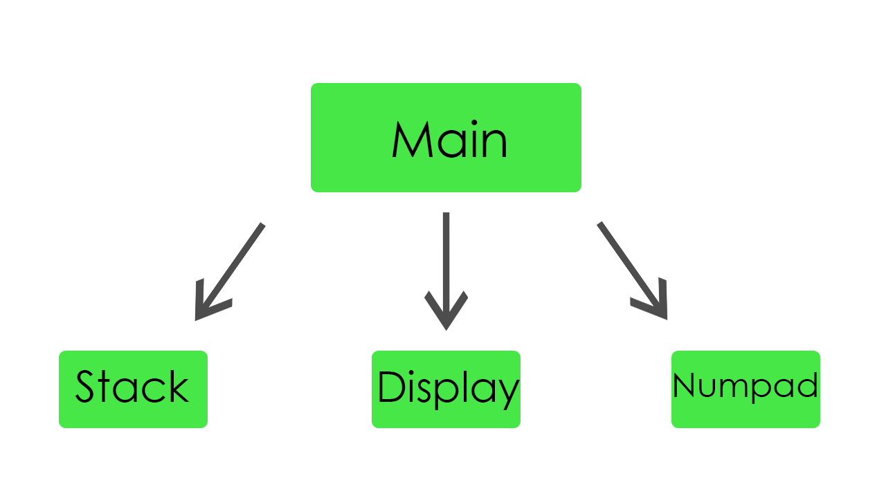
Cada membro da equipe escolheu um módulo para escrever. A tarefa de primeira ordem era implementar pilha, saída e entrada. Como foi determinado, começamos a trabalhar.
Stack
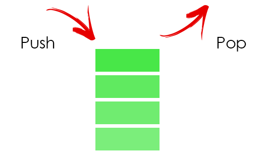
Na pilha, armazenamos todos os nossos operandos. Para armazená-los, dedicamos 32 palavras de memória.
Código do módulo de pilhamodule stack( //Just 50 MHz clock input clock, //Reset signal input reset, //PUSH operation control signal input push, //POP operation control signal input pop, //SWAP operation control signal input swap, //UPDATE operation control signal input write, //Value to write input [31:0] value, //Top element output [31:0] top, //Second element from stack top output [31:0] next, //Total elements count output [5:0] count, //Stack overflow error output error ); //Stack memory for 32 words reg [31:0] memory [0:31]; //Stack pointer on top element, indexing from 0 reg [5:0] pointer = 0; //First element by default is 0 initial memory[0] = 0; //Top stack element assign top = memory[pointer]; //Second element if such exists, 0 otherwise assign next = pointer == 0 ? 0 : memory[pointer - 1]; //Stack elements count assign count = pointer[4:0] + 1; //Stack overflow signal assign error = pointer[5]; always @(posedge clock) begin //Reseting if (reset) begin memory[0] <= 0; pointer <= 0; end //Remove one element form stack if (pop) pointer <= pointer - 1; //Swaps top and next elements if (swap) begin memory[pointer] <= memory[pointer - 1]; memory[pointer - 1] <= memory[pointer]; end //Update top element if (write) memory[pointer - pop] <= value; //Push new zero element on top if (push) begin pointer <= pointer + 1; //Here pointer is still not updated, so +1 memory[pointer + 1] <= 0; end end endmodule
É apenas uma pilha regular. Se um novo valor é pressionado, apenas aumenta o ponteiro e coloca esse valor no topo da pilha. Se um valor é retirado da pilha, diminui o ponteiro e atualiza o elemento superior.
Por conveniência, adicionamos um botão de redefinição para ter a oportunidade de reiniciar nosso programa durante a execução. Além disso, para a depuração foi adicionada uma oportunidade para capturar o erro de estouro de pilha.
Exibição
Neste módulo, implementamos todas as funcionalidades da tela. É capaz de mostrar dinamicamente resultados de nossos cálculos e também valores de entrada.

Aqui está o código para a exibição module display_bcd ( //Just 50 MHz clock input clock, //Switching hexademical and decimal representations input show_in_hex, //Asserted if something is going wrong, displaing error message input error, //Value to be displayed in binary format input [31:0] value, //Segments of display output [7:0] control, //LEDs of one segment output [7:0] leds ); // ###0### // # # // # # // 5 1 // # # // # # // ###6### // # # // # # // 4 2 // # # ### // # # #7# // ###3### ### //All representation of used symbols parameter D_0 = 8'b00111111; parameter D_1 = 8'b00000110; parameter D_2 = 8'b01011011; parameter D_3 = 8'b01001111; parameter D_4 = 8'b01100110; parameter D_5 = 8'b01101101; parameter D_6 = 8'b01111101; parameter D_7 = 8'b00000111; parameter D_8 = 8'b01111111; parameter D_9 = 8'b01101111; parameter D_DOT = 8'b10000000; parameter D_A = 8'b01110111; parameter D_B = 8'b01111100; parameter D_C = 8'b01011000; parameter D_D = 8'b01011110; parameter D_E = 8'b01111001; parameter D_F = 8'b01110001; parameter D_R = 8'b01010000; parameter D_O = 8'b01011100; parameter D_MINUS = 8'b01000000; parameter D_EMPTY = 8'b00000000; parameter D_E_CODE = 14; parameter D_R_CODE = 16; parameter D_O_CODE = 17; parameter D_MINUS_CODE = 18; parameter D_EMPTY_CODE = 31; //Delay counter, delaying 8192 clock cycles ~ 0.16 ms reg [12:0] counter = 0; //Saved Binary-Coded Decimal reg [31:0] r_bcd; //Number of segment that is active on current iteration reg [2:0] ctrl = 0; //Current digit shown on the current segment reg [4:0] digit; //Asserted for 1 cycle when conversion to Binary-Coded Decimal is done wire converted; //Intermediate Binary-Coded decimal value wire [31:0] bcd; //Decoded number digits wire [31:0] digits; //Number sign wire sign; //Digits from unsigned numbers wire [31:0] unsigned_number; bcd_convert #(32, 8) bcd_convert( .i_Clock(clock), .i_Binary(unsigned_number), .i_Start(1'b1), .o_BCD(bcd), .o_DV(converted)); //Get number sign assign sign = value[31]; //Get unsigned number assign unsigned_number = sign ? -value : value; //Switching final number representation assign digits = show_in_hex ? unsigned_number : r_bcd; //Constolling segments assign control = ~(1 << ctrl); reg [7:0] r_leds; //Controlling LEDs assign leds = ~r_leds; always @(posedge clock) begin case (digit) 0: r_leds <= D_0; 1: r_leds <= D_1; 2: r_leds <= D_2; 3: r_leds <= D_3; 4: r_leds <= D_4; 5: r_leds <= D_5; 6: r_leds <= D_6; 7: r_leds <= D_7; 8: r_leds <= D_8; 9: r_leds <= D_9; 10: r_leds <= D_A; 11: r_leds <= D_B; 12: r_leds <= D_C; 13: r_leds <= D_D; 14: r_leds <= D_E; 15: r_leds <= D_F; 16: r_leds <= D_R; 17: r_leds <= D_O; 18: r_leds <= D_MINUS; default: r_leds <= D_EMPTY; endcase if (error) //Display error message case(ctrl) 0: digit <= D_R_CODE; 1: digit <= D_O_CODE; 2: digit <= D_R_CODE; 3: digit <= D_R_CODE; 4: digit <= D_E_CODE; 5: digit <= D_EMPTY_CODE; 6: digit <= D_EMPTY_CODE; 7: digit <= D_EMPTY_CODE; endcase else //Select current digit case(ctrl) 0: digit <= digits[3:0]; 1: digit <= digits[31:4] ? digits[7:4] : D_EMPTY_CODE; 2: digit <= digits[31:8] ? digits[11:8] : D_EMPTY_CODE; 3: digit <= digits[31:12] ? digits[15:12] : D_EMPTY_CODE; 4: digit <= digits[31:16] ? digits[19:16] : D_EMPTY_CODE; 5: digit <= digits[31:20] ? digits[23:20] : D_EMPTY_CODE; 6: digit <= digits[31:24] ? digits[27:24] : D_EMPTY_CODE; 7: digit <= sign ? D_MINUS_CODE : (digits[31:28] ? digits[31:28] : D_EMPTY_CODE); endcase //Increase current delay counter <= counter + 1; //Delay is done, increase segment number if (counter == 13'b1000000000000) ctrl <= ctrl + 1; //Save converted Binary-Coded Decimal if (converted) r_bcd <= bcd; end endmodule
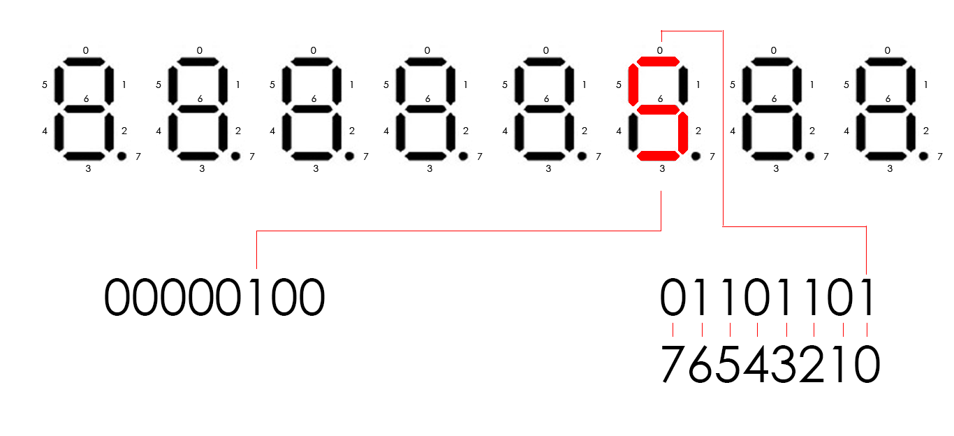
O Cyclone IV possui oito displays de oito segmentos. Eles são controlados por 16 pinos. Oito pinos controlam segmentos em cada tela (vamos chamá-lo de led) e outros oito pinos controlam qual tela estará ativa (apenas chame de controle). Por exemplo, se precisarmos mostrar o dígito 5 no terceiro monitor, o controle deve ser 00000100 e o led deve ser 01101101 (de acordo com o esquema no código). Para exibir vários dígitos diferentes em telas diferentes, precisamos acender periodicamente cada tela. Assim, a cada 8192 ciclos de clock, movemos à esquerda logicamente por 1 bit nossa saída de controle, que é inicialmente igual a 00000001. Quando a movemos, alteramos o número a ser exibido atualmente. Isso acontece tão rápido que nosso olho não pode ver as alterações, portanto, podemos mostrar dígitos diferentes em cada exibição.
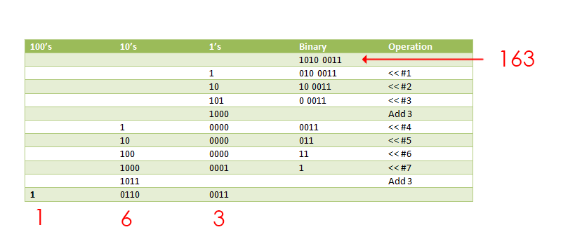
À medida que passamos para este número binário do módulo, precisamos representá-lo como dígitos separados. Para esse fim,
encontramos um módulo que o utiliza, usando o algoritmo de dupla dabble. Ele recebe como entrada nosso número binário e o retorna como um decimal codificado binário (4 bits por dígito).
Aqui está o código para ele module bcd_convert #(parameter INPUT_WIDTH, parameter DECIMAL_DIGITS) ( input i_Clock, input [INPUT_WIDTH-1:0] i_Binary, input i_Start, // output [DECIMAL_DIGITS*4-1:0] o_BCD, output o_DV ); parameter s_IDLE = 3'b000; parameter s_SHIFT = 3'b001; parameter s_CHECK_SHIFT_INDEX = 3'b010; parameter s_ADD = 3'b011; parameter s_CHECK_DIGIT_INDEX = 3'b100; parameter s_BCD_DONE = 3'b101; reg [2:0] r_SM_Main = s_IDLE; // The vector that contains the output BCD reg [DECIMAL_DIGITS*4-1:0] r_BCD = 0; // The vector that contains the input binary value being shifted. reg [INPUT_WIDTH-1:0] r_Binary = 0; // Keeps track of which Decimal Digit we are indexing reg [DECIMAL_DIGITS-1:0] r_Digit_Index = 0; // Keeps track of which loop iteration we are on. // Number of loops performed = INPUT_WIDTH reg [7:0] r_Loop_Count = 0; wire [3:0] w_BCD_Digit; reg r_DV = 1'b0; always @(posedge i_Clock) begin case (r_SM_Main) // Stay in this state until i_Start comes along s_IDLE : begin r_DV <= 1'b0; if (i_Start == 1'b1) begin r_Binary <= i_Binary; r_SM_Main <= s_SHIFT; r_BCD <= 0; end else r_SM_Main <= s_IDLE; end // Always shift the BCD Vector until we have shifted all bits through // Shift the most significant bit of r_Binary into r_BCD lowest bit. s_SHIFT : begin r_BCD <= r_BCD << 1; r_BCD[0] <= r_Binary[INPUT_WIDTH-1]; r_Binary <= r_Binary << 1; r_SM_Main <= s_CHECK_SHIFT_INDEX; end // Check if we are done with shifting in r_Binary vector s_CHECK_SHIFT_INDEX : begin if (r_Loop_Count == INPUT_WIDTH-1) begin r_Loop_Count <= 0; r_SM_Main <= s_BCD_DONE; end else begin r_Loop_Count <= r_Loop_Count + 1; r_SM_Main <= s_ADD; end end // Break down each BCD Digit individually. Check them one-by-one to // see if they are greater than 4. If they are, increment by 3. // Put the result back into r_BCD Vector. s_ADD : begin if (w_BCD_Digit > 4) begin r_BCD[(r_Digit_Index*4)+:4] <= w_BCD_Digit + 3; end r_SM_Main <= s_CHECK_DIGIT_INDEX; end // Check if we are done incrementing all of the BCD Digits s_CHECK_DIGIT_INDEX : begin if (r_Digit_Index == DECIMAL_DIGITS-1) begin r_Digit_Index <= 0; r_SM_Main <= s_SHIFT; end else begin r_Digit_Index <= r_Digit_Index + 1; r_SM_Main <= s_ADD; end end s_BCD_DONE : begin r_DV <= 1'b1; r_SM_Main <= s_IDLE; end default : r_SM_Main <= s_IDLE; endcase end // always @ (posedge i_Clock) assign w_BCD_Digit = r_BCD[r_Digit_Index*4 +: 4]; assign o_BCD = r_BCD; assign o_DV = r_DV; endmodule // Binary_to_BCD
Este módulo funciona com um algoritmo muito interessante. Ele muda todos os bits do número para a esquerda, um por um e, se os 4 primeiros bits forem maiores que 4 em decimal, adicionará decimal 3 a eles.
Numpad
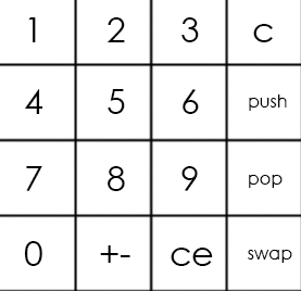
Este módulo funciona com o teclado numérico. Ele lê o valor do numbpad e o passa para o módulo principal. Temos dois estados do teclado. Eles podem ser trocados pressionando um dos botões no fpga.
O teclado principal é assim:
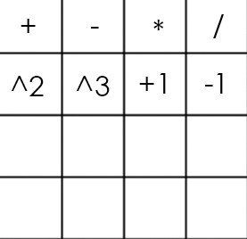
E a alternativa assim:
O código do numpad module numpad ( //Just 50 MHz clock input clock, //Alternative keyboard input alt_key, //Alternative keyboard indicator output alt_led, //Numpad rows input [3:0] rows, //Numpad columns output [3:0] columns, //State change description [5:5] - is_changed, [4:4] - keyboard, [3:0] - button output [5:0] value ); // col 0 col 1 col 2 col 3 // // ############################# // # # # # # // # 1(0) # 2(4) # 3(8) # A(12)# row 0 // # # # # # // ############################# // # # # # # // # 4(1) # 5(5) # 6(9) # B(13)# row 1 // # # # # # // ############################# // # # # # # // # 7(2) # 8(6) # 9(10)# C(14)# row 2 // # # # # # // ############################# // # # # # # // # 0(3) # F(7) # E(11)# D(15)# row 3 // # # # # # // ############################# parameter BTN_EMPTY = 6'b000000; //Previous pressed button reg [5:0] prev = 0; //Current pressed button reg [5:0] cur = 0; //Current column number reg [1:0] col = 0; //Counter for delay reg [8:0] counter = 0; //Rows pressed flags reg [3:0] pressed = 0; //Is alternative keyboard reg is_alt = 0; //Alt key on prev clock cycle reg prev_alt_key = 0; //Controlling column assign columns = ~(1 << col); assign alt_led = ~is_alt; always @(posedge clock) begin //Increase counter counter <= counter + 1; //Evaluating alternative keyboard signal if (value != BTN_EMPTY) is_alt <= 0; else is_alt <= (alt_key == 1 && prev_alt_key == 0) ? ~is_alt : is_alt; prev_alt_key <= alt_key; if (counter == 9'b1111111111) begin //Evaluating current button case(~rows) 4'b0001: begin pressed[col] <= 1; cur <= {1'b1, ~is_alt, col, 2'b00}; end 4'b0010: begin pressed[col] <= 1; cur <= {1'b1, ~is_alt, col, 2'b01}; end 4'b0100: begin pressed[col] <= 1; cur <= {1'b1, ~is_alt, col, 2'b10}; end 4'b1000: begin pressed[col] <= 1; cur <= {1'b1, ~is_alt, col, 2'b11}; end default: begin pressed[col] <= 0; cur <= pressed ? cur : BTN_EMPTY; end endcase end //increase column number when counter is 9'011111111, using different edges of counter[8] to let counter pass through zero, to assert wire value if need if (counter == 9'b011111111) begin //Saving previous button every 4 iterations if (&col) prev <= cur; col <= col + 1; end end //Evaluating state change //Comparing current and previous states without keyboard bit assign value = (counter == 9'b000000000 && col == 2'b11 && {prev[5], prev[3:0]} != {cur[5], cur[3:0]}) ? cur : BTN_EMPTY; endmodule
Portanto, o numpad é um esquema que contém 16 botões (4 linhas e 4 colunas). Para obter o número do botão pressionado, precisamos de 4 saídas (sejam colunas) e 4 entradas (linhas). Passamos a tensão para cada coluna periodicamente e, se o botão for pressionado, o circuito será fechado e determinada linha será verdadeira como entrada. A combinação do número da coluna e o número da linha determina exclusivamente o nosso botão.
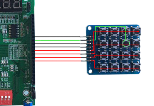
Se usarmos o teclado principal no exemplo acima, obteremos o número 5 como entrada.
Módulo principal
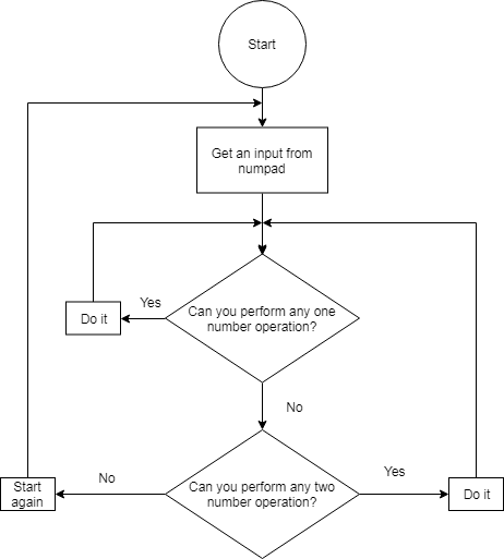
O módulo principal conecta todas as partes e efetivamente faz cálculos.
O módulo principal aqui module main( //Just 50 MHz clock input clock, //Reset signal input reset, //Representation switch input show_in_hex, //Show stack elements count switch input show_count, //Button, switches to operations keyboard input alt_numpad_key, //Alternative keyboard indicator output alt_numpad_led, //Numpad rows and columns input [3:0] numpad_rows, output [3:0] numpad_columns, //Display and display control output [7:0] display_leds, output [7:0] display_control ); // 1 2 3 C // 4 5 6 PUSH // 7 8 9 POP // 0 +- CE SWAP parameter BTN_0 = 6'b110011; parameter BTN_1 = 6'b110000; parameter BTN_2 = 6'b110100; parameter BTN_3 = 6'b111000; parameter BTN_4 = 6'b110001; parameter BTN_5 = 6'b110101; parameter BTN_6 = 6'b111001; parameter BTN_7 = 6'b110010; parameter BTN_8 = 6'b110110; parameter BTN_9 = 6'b111010; parameter BTN_CLEAR_DIGIT = 6'b111100; parameter BTN_PUSH = 6'b111101; parameter BTN_POP = 6'b111110; parameter BTN_SWAP = 6'b111111; parameter BTN_CLEAR_NUMBER = 6'b111011; parameter BTN_UNARY_MINUS = 6'b110111; // + - * / // sqr cbe inc dec parameter BTN_ADDITION = 6'b100000; parameter BTN_SUBTRACTION = 6'b100100; parameter BTN_MULTIPLICATION = 6'b101000; parameter BTN_DIVISION = 6'b101100; parameter BTN_SQUARE = 6'b100001; parameter BTN_CUBE = 6'b100101; parameter BTN_INCREMENT = 6'b101001; parameter BTN_DECREMENT = 6'b101101; //Numpad state wire [5:0] pressed; //Stack elements count wire [5:0] count; //First and second stack elements wire [31:0] top, next; wire stack_error; //Evaluated new value reg [31:0] new_value; //Stack control signals reg write, push, pop, swap; reg arithmetic_error = 0; numpad numpad( .clock (clock), .alt_key (~alt_numpad_key), .alt_led (alt_numpad_led), .rows (numpad_rows), .columns (numpad_columns), .value (pressed) ); stack stack( .clock (clock), .reset (~reset), .push (push), .pop (pop), .swap (swap), .write (write), .value (new_value), .top (top), .next (next), .count (count), .error (stack_error) ); display_bcd display( .clock (clock), .error (stack_error || arithmetic_error), .show_in_hex (show_in_hex), .value (show_count ? count : top), .control (display_control), .leds (display_leds) ); // Division result wire [31:0] res; assign res = ((next[31] ? -next : next) / (top[31] ? -top : top)); always @(posedge clock) begin //Reseting arithmetic error if (~reset) arithmetic_error <= 0; case (pressed) BTN_0: begin write <= 1; new_value <= top * 10; end BTN_1: begin write <= 1; new_value <= top * 10 + (top[31] ? -1 : 1); end BTN_2: begin write <= 1; new_value <= top * 10 + (top[31] ? -2 : 2); end BTN_3: begin write <= 1; new_value <= top * 10 + (top[31] ? -3 : 3); end BTN_4: begin write <= 1; new_value <= top * 10 + (top[31] ? -4 : 4); end BTN_5: begin write <= 1; new_value <= top * 10 + (top[31] ? -5 : 5); end BTN_6: begin write <= 1; new_value <= top * 10 + (top[31] ? -6 : 6); end BTN_7: begin write <= 1; new_value <= top * 10 + (top[31] ? -7 : 7); end BTN_8: begin write <= 1; new_value <= top * 10 + (top[31] ? -8 : 8); end BTN_9: begin write <= 1; new_value <= top * 10 + (top[31] ? -9 : 9); end BTN_CLEAR_DIGIT: begin write <= 1; new_value <= top / 10; end BTN_CLEAR_NUMBER: begin write <= 1; new_value <= 0; end BTN_PUSH: begin push <= 1; end BTN_POP: begin pop <= 1; end BTN_SWAP: begin swap <= 1; end BTN_UNARY_MINUS: begin write <= 1; new_value <= -top; end BTN_ADDITION: begin pop <= 1; write <= 1; new_value <= next + top; end BTN_SUBTRACTION: begin pop <= 1; write <= 1; new_value <= next - top; end BTN_MULTIPLICATION: begin pop <= 1; write <= 1; new_value <= next * top; end BTN_DIVISION: begin pop <= 1; write <= 1; new_value <= (next[31] ^ top[31] ? -res : res); arithmetic_error <= ~(|top); end BTN_SQUARE: begin write <= 1; new_value <= top * top; end BTN_CUBE: begin write <= 1; new_value <= top * top * top; end BTN_INCREMENT: begin write <= 1; new_value <= top + 1; end BTN_DECREMENT: begin write <= 1; new_value <= top - 1; end default: // Nothing usefull is pressed begin write <= 0; push <= 0; pop <= 0; swap <= 0; end endcase end endmodule
O bloco "always" contém uma declaração de caso que está escolhendo a operação, dependendo de qual botão do teclado numérico é pressionado. Se um botão com o dígito pressionado, esse dígito vai para o topo da pilha. Se precisarmos inserir o número que tem mais de um dígito, o número superior na pilha é multiplicado por 10 e esse valor multiplicado vai para o topo da pilha. Se o botão com uma operação for pressionado, esta operação será aplicada aos dois primeiros números da pilha.
Durante o teste, descobrimos uma coisa interessante sobre a divisão em Verilog. Por alguma estranha razão, se tentarmos dividir dois números negativos, a operação resultará em zero como resultado. Portanto, para corrigi-lo, tivemos que adicionar um ramo para processar esse caso explicitamente.
Conclusão
Aqui está o vídeo, que demonstra o trabalho da calculadora. Além disso,
aqui está o github do nosso projeto.
Estudar Verilog aumentou drasticamente nossa compreensão da arquitetura do computador. Além disso, trabalhar em equipe nos ajudou a desenvolver habilidades básicas para o trabalho em equipe.
Autores: Fedoseev Kirill, Yuloskov Artem.