1. Introdução
Criamos um código verilog sintetizável para calcular uma raiz de cubo inteiro de um número inteiro via algoritmo de busca binária. Este código foi testado na placa FPGA Cyclone IV. Aqui você pode ler sobre implementação e entender como as coisas funcionam.
Link do Github:
raiz do cuboO que é uma raiz de cubo?
A raiz do cubo de um número
y é um número
x tal que
$$ display $$ x ^ 3 = y $$ display $$
Exemplos:
$$ display $$ \ sqrt [3] {8} = 2 \\ \ sqrt [3] {27} = 3 \\ \ sqrt [3] {64} = 4 $$ display $$
Portanto, em nossa implementação, usamos uma
raiz de cubo inteiro .
Isso significa que uma raiz de cubo de um número inteiro
x é outro número inteiro tal que:
$$ exibir $$ a ^ 3 \ leqslant x, \\ (a + 1) ^ 3 \ geqslant x $$ exibir $$
Exemplos:
exibição em $$ $$ \ sqrt [3] {26} = 2 \\ \ sqrt [3] {28} = 3 \\ \ sqrt [3] {63} = 3 \\ \ sqrt [3] {65} = 4 $$ exibir $$
Lógica principal
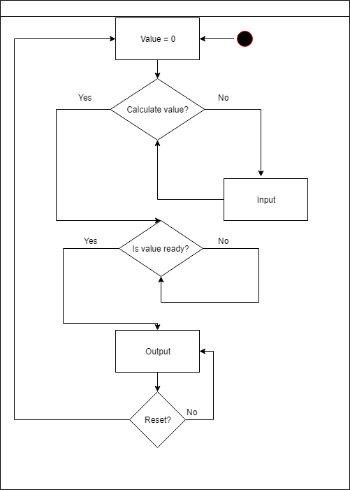
O módulo principal é responsável por todas as ações com um número durante a entrada.
Possui 4 ações possíveis:
- multiplicar incremento por 10
- divida o incremento por 10 (o incremento é sempre não inferior a 1)
- aumentar número
- diminuir número
Módulo principalmodule cube_root( input inc, input sub, input next, input prev, input enter, input clk, output wire [7:0] leds, output wire [7:0] control ); reg signed [31:0] exit; wire ready; wire [31:0] res; reg zero = 0; // input // reg inc1 = 0; reg next1 = 0; reg prev1 = 0; reg sub1 = 0; reg enter1 = 0; reg [31:0] decimal = 1; ////////// reg [31:0] to_display; display_bcd display( .clk(clk), .value(ready == 0 ? exit : res), .control(control), .leds(leds) ); calculate calc( .clk(clk), .ready_to_calc(~enter), .num(exit), .ready(ready), .res(res) ); always @(posedge clk) begin if (enter == 1) begin if ((inc1 == 1'b0) && (~inc == 1'b1)) begin exit = exit + decimal; end inc1 = ~inc; if ((sub1 == 1'b0) && (~sub == 1'b1)) begin if (exit > 0) begin exit = exit - decimal; end end sub1 = ~sub; if ((next1 == 1'b0) && (~next == 1'b1)) begin decimal = decimal * 10; end next1 = ~next; if ((prev1 == 1'b0) && (~prev == 1'b1)) begin if (decimal >= 1 && decimal <= 9) begin decimal = 1; end else begin decimal = decimal / 10; end end prev1 = ~prev; end else begin if (ready == 1'b1) begin exit = 0; decimal = 1; end end end endmodule
No módulo principal
cube_root , também existem outros dois módulos:
calcular e
exibir_bcd . O primeiro faz todos os cálculos necessários, enquanto o segundo módulo é responsável por exibir os valores de entrada e saída durante a execução do programa.
Agora, vamos entender como eles funcionam.
Calcular módulo
O módulo de cálculo usa um algoritmo de pesquisa binária. E quando todos os cálculos são feitos, ele define a variável
ready como 1. É um sinal para o módulo de exibição dar a resposta.
Calcular módulo module calculate( input clk, input ready_to_calc, input [31:0] num, output reg ready, output [31:0] res ); integer mid; integer start; integer final; integer counter; assign res = mid; always @(posedge clk) begin if (ready_to_calc == 1) begin if (ready == 0) begin mid = (start + final )/2; if ((mid*mid*mid) > num) begin final = mid; end else begin start = mid; end if (counter == 27) begin ready = 1; counter = 0; end else begin counter = counter + 1; end end end else begin final = 465; start = 0; ready = 0; counter = 0; end end endmodule
Por que este módulo faz exatamente 27 iterações?- O número máximo de entrada é 99999999. Portanto, o número máximo possível de iterações é
$ inline $ \ log_2 99999999 = 26,575424745 \ aproximadamente 27 $ inline $
Por que o limite superior da pesquisa binária é inicializado por 465?- Porque é o número máximo que podemos obter como resultado.
$ inline $ \ sqrt [3] {99999999} \ aproximadamente 464 $ inline $
Módulo de exibição
Este módulo é responsável pelo desempenho. Ele usa oito displays de oito segmentos e eles são manipulados por 16 pinos. Onde 8 pinos são "responsáveis" por leds específicos no visor e outros 8 são segmentos de controle, eles representam dígitos distintos.
Então, passamos um valor inteiro que queremos exibir para este módulo. Em seguida, ele passa esse valor para o módulo
Binary_to_BCD , que converte o número binário no decimal codificado em binário usando o
algoritmo Double Dabble . Depois disso, o valor convertido se torna fácil de exibir.
Módulo de exibição module display_bcd ( input clk, input [31:0] value, output [7:0] control, output [7:0] leds ); bcd_convert #(32, 8) bcd_convert( .i_Clock(clk), .i_Binary(value_temp), .i_Start(1'b1), .o_BCD(bcd_number), .o_DV(bcd_ready) ); integer delay = 0; integer final_bcd; reg [2:0] ctrl = 0; reg [4:0] digit; wire bcd_ready; wire [31:0] bcd_number; wire [31:0] digits; assign digits = final_bcd; wire [31:0] value_temp; assign value_temp = value; assign control = ~(1 << ctrl); assign leds = ~ (digit == 0 ? 8'b00111111 : (digit == 1 ? 8'b00000110 : (digit == 2 ? 8'b01011011 : (digit == 3 ? 8'b01001111 : (digit == 4 ? 8'b01100110 : (digit == 5 ? 8'b01101101 : (digit == 6 ? 8'b01111101 : (digit == 7 ? 8'b00000111 : (digit == 8 ? 8'b01111111 : (digit == 9 ? 8'b01101111 : 8'b00000000)))))))))); always @(posedge clk) begin if (bcd_ready) final_bcd = bcd_number; case(ctrl) 0: digit = digits[3:0]; 1: digit = digits[31:4] ? digits[7:4] : 10; 2: digit = digits[31:8] ? digits[11:8] : 10; 3: digit = digits[31:12] ? digits[15:12] : 10; 4: digit = digits[31:16] ? digits[19:16] : 10; 5: digit = digits[31:20] ? digits[23:20] : 10; 6: digit = digits[31:24] ? digits[27:24] : 10; 7: digit = digits[31:28] ? digits[31:28] : 10; endcase delay = delay + 1; if (delay == 10000) ctrl = ctrl + 1; end endmodule
Conversão bcd module bcd_convert #(parameter INPUT_WIDTH, parameter DECIMAL_DIGITS) ( input i_Clock, input [INPUT_WIDTH-1:0] i_Binary, input i_Start, output [DECIMAL_DIGITS*4-1:0] o_BCD, output o_DV ); parameter s_IDLE = 3'b000; parameter s_SHIFT = 3'b001; parameter s_CHECK_SHIFT_INDEX = 3'b010; parameter s_ADD = 3'b011; parameter s_CHECK_DIGIT_INDEX = 3'b100; parameter s_BCD_DONE = 3'b101; reg [2:0] r_SM_Main = s_IDLE; // The vector that contains the output BCD reg [DECIMAL_DIGITS*4-1:0] r_BCD = 0; // The vector that contains the input binary value being shifted. reg [INPUT_WIDTH-1:0] r_Binary = 0; // Keeps track of which Decimal Digit we are indexing reg [DECIMAL_DIGITS-1:0] r_Digit_Index = 0; // Keeps track of which loop iteration we are on. // Number of loops performed = INPUT_WIDTH reg [7:0] r_Loop_Count = 0; wire [3:0] w_BCD_Digit; reg r_DV = 1'b0; always @(posedge i_Clock) begin case (r_SM_Main) // Stay in this state until i_Start comes along s_IDLE : begin r_DV <= 1'b0; if (i_Start == 1'b1) begin r_Binary <= i_Binary; r_SM_Main <= s_SHIFT; r_BCD <= 0; end else r_SM_Main <= s_IDLE; end // Always shift the BCD Vector until we have shifted all bits through // Shift the most significant bit of r_Binary into r_BCD lowest bit. s_SHIFT : begin r_BCD <= r_BCD << 1; r_BCD[0] <= r_Binary[INPUT_WIDTH-1]; r_Binary <= r_Binary << 1; r_SM_Main <= s_CHECK_SHIFT_INDEX; end // Check if we are done with shifting in r_Binary vector s_CHECK_SHIFT_INDEX : begin if (r_Loop_Count == INPUT_WIDTH-1) begin r_Loop_Count <= 0; r_SM_Main <= s_BCD_DONE; end else begin r_Loop_Count <= r_Loop_Count + 1; r_SM_Main <= s_ADD; end end // Break down each BCD Digit individually. Check them one-by-one to // see if they are greater than 4. If they are, increment by 3. // Put the result back into r_BCD Vector. s_ADD : begin if (w_BCD_Digit > 4) begin r_BCD[(r_Digit_Index*4)+:4] <= w_BCD_Digit + 3; end r_SM_Main <= s_CHECK_DIGIT_INDEX; end // Check if we are done incrementing all of the BCD Digits s_CHECK_DIGIT_INDEX : begin if (r_Digit_Index == DECIMAL_DIGITS-1) begin r_Digit_Index <= 0; r_SM_Main <= s_SHIFT; end else begin r_Digit_Index <= r_Digit_Index + 1; r_SM_Main <= s_ADD; end end s_BCD_DONE : begin r_DV <= 1'b1; r_SM_Main <= s_IDLE; end default : r_SM_Main <= s_IDLE; endcase end // always @ (posedge i_Clock) assign w_BCD_Digit = r_BCD[r_Digit_Index*4 +: 4]; assign o_BCD = r_BCD; assign o_DV = r_DV; endmodule // Binary_to_BCD
Autores: Tyurin Leonid, Tikhonov Nikita.