70年前,1947年12月16日,在威廉·肖克利(William Shockley)的指导下,约翰·巴丁(John Bardin)和沃尔特·布拉顿(Walter Brattain)在贝尔实验室(Bell Labs)实验室创建了第一个可操作的双极晶体管。12月23日,Brattain向他的同事展示了第一台晶体管放大器。因此,这一天通常称为晶体管日。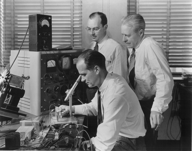 无需谈论此事件的重要性。晶体管被认为是20世纪最重要的发明之一,没有它,计算机仍然可以在灯和继电器上工作,并占据整个建筑物。肖克利,巴丁和布雷顿因其工作于1956年获得诺贝尔物理学奖。多年来,晶体管已小型化到只有几个原子。每个处理器都有数十亿个晶体管,因此该晶体管可以称为人类创造的最庞大的设备。但是晶体管为我们做了什么工作?让我们进行一次心理之旅:我们将跟踪从一些高级指尖到我们生日的道路-晶体管。以什么为起点?好吧,至少要画一个habrakat按钮。
HTML和CSS
按钮由背景像素,文本和边框组成。在代码中,由<a>标记设置,并对其应用CSS布局规则。例如,将CSS规则应用于边框到圆角:border-radius: 3px;
 因此,边界由四个线段和四个弧(一个圆的“四分之一”)组成。
浏览器
为了进行研究,我选择了我最喜欢的Firefox。在FF开始绘制按钮之前,他需要做很多工作来解析和计算元素的位置:- 通过网络下载HTML,解析并编写DOM树
- 通过CSS网络下载,进行词法分析,解析
- 将基于优先级和继承的规则绑定到页面元素
- 对于所有可见的DOM节点,组成其矩形区域的树-框架。
- 对于框架,请计算尺寸和位置(请参阅视频)
- 考虑到z索引和内容类型(<画布>,SVG,<视频>),从框架组成图层。
- 按以下顺序创建图形列表:背景颜色,背景图像,边框,后代,轮廓。
我们不会详细介绍这些步骤。在它们之后是必要元素的实际图纸。nsCSSRenderingBorders.cpp
文件负责绘制边框。绘制边框的一般功能称为(会想到的):DrawBorders()。该功能为各种情况选择最佳渲染方法。我们有一个相对简单的例子:存在边界半径,但是所有边上的边界都是实心且具有相同的颜色。如果我们if (allBordersSame &&
mCompositeColors[0] == nullptr &&
mBorderStyles[0] == NS_STYLE_BORDER_STYLE_SOLID &&
!mAvoidStroke &&
!mNoBorderRadius)
{
gfxRect outerRect = ThebesRect(mOuterRect);
RoundedRect borderInnerRect(outerRect, mBorderRadii);
borderInnerRect.Deflate(mBorderWidths[eSideTop],
mBorderWidths[eSideBottom],
mBorderWidths[eSideLeft],
mBorderWidths[eSideRight]);
RefPtr<PathBuilder> builder = mDrawTarget->CreatePathBuilder();
AppendRoundedRectToPath(builder, mOuterRect, mBorderRadii, true);
AppendRoundedRectToPath(builder, ToRect(borderInnerRect.rect), borderInnerRect.corners, false);
RefPtr<Path> path = builder->Finish();
mDrawTarget->Fill(path, color);
return;
}
还有很多更复杂的选项,例如停靠在具有不同类型的虚线和虚线边框的边框半径的角落中,请参见DrawDashedOrDottedCorner()。完全在代码中但是回到我们的前提。从注释中我们了解到,在这种情况下,边框是使用内部和外部两个矩形绘制的,然后用所需的颜色填充创建的路径(路径)。AppendRoundedRectToPath(builder, mOuterRect, mBorderRadii, true);
AppendRoundedRectToPath(builder, ToRect(borderInnerRect.rect), borderInnerRect.corners, false);
RefPtr<Path> path = builder->Finish();
mDrawTarget->Fill(path, color);
转到gfx / 2d / PathHelpers.cpp中的AppendRoundedRectToPath()。从函数的注释中我们得知,贝塞尔曲线在四个控制点上绘制了拐角。贝塞尔曲线通常用在计算机图形学中,包括绘制圆弧和椭圆弧。当我们从注释中进一步学习时,有很多选择用于选择控制点以构建曲线的选项。在这种情况下,我们需要点0和3属于矩形的边,点0、1和C在一条直线上,点3、2和C在另一条直线上。参见下图: 我们仍然需要计算段01 / 0C和32 / 3C的长度之比。在这里,作者使用近似计算并获得魔术常数alpha:
const Float alpha = Float(0.55191497064665766025);
不幸的是,带有注释引用的检查点选择算法的文章不在公共领域。但通常应注意,在计算机图形学中,算法通常使用近似值来提高性能。例如,Brezenham算法允许您通过求解方程y = f(x)来绘制“不是在额头上”的段和圆,而是使用更多狡猾的整数运算。填充等相同的东西在该循环中,我们从一个拐角到另一个拐角,使用alpha来计算控制点的坐标,最后调用绘制边界线和拐角弧的函数:aPathBuilder->LineTo(p0);
aPathBuilder->BezierTo(p1, p2, p3);
完整的AppendRoundedRectToPath()代码void
AppendRoundedRectToPath(PathBuilder* aPathBuilder,
const Rect& aRect,
const RectCornerRadii& aRadii,
bool aDrawClockwise)
{
const Float alpha = Float(0.55191497064665766025);
typedef struct { Float a, b; } twoFloats;
twoFloats cwCornerMults[4] = { { -1, 0 },
{ 0, -1 },
{ +1, 0 },
{ 0, +1 } };
twoFloats ccwCornerMults[4] = { { +1, 0 },
{ 0, -1 },
{ -1, 0 },
{ 0, +1 } };
twoFloats *cornerMults = aDrawClockwise ? cwCornerMults : ccwCornerMults;
Point cornerCoords[] = { aRect.TopLeft(), aRect.TopRight(),
aRect.BottomRight(), aRect.BottomLeft() };
Point pc, p0, p1, p2, p3;
if (aDrawClockwise) {
aPathBuilder->MoveTo(Point(aRect.X() + aRadii[RectCorner::TopLeft].width,
aRect.Y()));
} else {
aPathBuilder->MoveTo(Point(aRect.X() + aRect.Width() - aRadii[RectCorner::TopRight].width,
aRect.Y()));
}
for (int i = 0; i < 4; ++i) {
int c = aDrawClockwise ? ((i+1) % 4) : ((4-i) % 4);
int i2 = (i+2) % 4;
int i3 = (i+3) % 4;
pc = cornerCoords[c];
if (aRadii[c].width > 0.0 && aRadii[c].height > 0.0) {
p0.x = pc.x + cornerMults[i].a * aRadii[c].width;
p0.y = pc.y + cornerMults[i].b * aRadii[c].height;
p3.x = pc.x + cornerMults[i3].a * aRadii[c].width;
p3.y = pc.y + cornerMults[i3].b * aRadii[c].height;
p1.x = p0.x + alpha * cornerMults[i2].a * aRadii[c].width;
p1.y = p0.y + alpha * cornerMults[i2].b * aRadii[c].height;
p2.x = p3.x - alpha * cornerMults[i3].a * aRadii[c].width;
p2.y = p3.y - alpha * cornerMults[i3].b * aRadii[c].height;
aPathBuilder->LineTo(p0);
aPathBuilder->BezierTo(p1, p2, p3);
} else {
aPathBuilder->LineTo(pc);
}
}
aPathBuilder->Close();
}
但是,这一切都取决于Mozilla使用的2D图形的后端。图形引擎
Gecko使用与平台无关的Moz2D库,而该库又可以使用后端之一:Cairo,Skia,Direct2D,Quartz和NV Path。例如,Windows可使用Direct2D,Cairo,Skia。Skia也是Chromium后端。您可以在about:config中更改后端。后端又可以读取CPU上的所有内容,或者可以在某种程度上使用GPU硬件加速。例如,Skia有自己的OpenGL后端-Ganesh。Direct2D代码已关闭,因此我们最好打开Skia并查看其作用。调用绘制三次曲线SkPath :: cubeTo的函数。要构建曲线,可通过de Casteljo算法将其划分为多个直线段,并进行实际绘制(请参见core / SkGeometry.cpp)。机器码
老实说,我并没有完全了解Skia的内部原理,所以我退后了一步-回到AppendRoundedRectToPath(),在其中所有操作都对整数执行-会更容易吗?打开反汇编代码后,我们必须在其中找到加法运算。...
142B1863 00 00 add byte ptr [eax],al
142B1865 00 8D 43 FF 0F 84 add byte ptr [ebp-7BF000BDh],cl
142B186B 67 01 00 add dword ptr [bx+si],eax
142B186E 00 99 0F 57 C9 F7 add byte ptr [ecx-836A8F1h],bl
142B1874 F9 stc
142B1875 8B C3 mov eax,ebx
142B1877 8B CA mov ecx,edx
142B1879 99 cdq
142B187A F7 7C 24 28 idiv eax,dword ptr [esp+28h]
...
是的我什至很容易就猜到,即使ADD远离ASM的人也要负责添加操作。采取的第一步:142B1863 00 00 add byte ptr [eax],al0x142B1863 -地址在存储器中为0x00 - 操作码 - CPU指令代码。此Mozilla在x86下编译,并打开x86指令表,我们将看到代码00表示对ADD助记符进行8位加法运算。第一个操作数可以是寄存器或随机存取存储单元,第二个可以是寄存器。第一个操作数被添加到第二个操作数,结果被写入第一个。为了以防万一,我将说明该寄存器是处理器内部的超高速RAM存储器,例如,用于存储中间计算结果。第二个字节也是0x00,称为MOD-REG-R / M。其位指定操作数和寻址方法。 MOD = 00b结合R / M = 000b表示使用间接寻址REG = 000b表示使用AL寄存器(EAX寄存器的低8位)[eax]-表示添加是与RAM单元相加的,其地址在EAX寄存器中。处理器如何处理ADD命令?
中央处理器
基于对Skylake微体系结构的描述,我编译了一个(极其简化的)步骤列表:- X86指令从32KB L1指令高速缓存中提取到16字节预编码缓冲区中
- 预编码的命令组织在指令队列中(大小为2x25),并进入解码器
- x86 1-4 (µOPs). ADD 1 µOP ALU (- ) 2 µOP AGU ( ) (., ). 86 .
- Allocation Queue (IDQ). , Loop Stream Detector — .
- : , . . .
- 微操作由Unified Scheduler管理器执行,该管理器决定在何时何地发送操作以不按接收顺序进行执行。每个端口的后面是一个执行器。我们的微操作将转到ALU和AGU。
 SkyLake的核心。图片来自en.wikichip.org。我再说一遍,这是我非常简化的描述,并不假装是准确和完整的。要获得更多参考,我建议阅读通过处理器的计算管道进行的“旅途之旅”和“英特尔酷睿i7的处理器”一文。
ALU
现在,了解ALU中发生的事情将很有趣:这些数字是如何累加的?不幸的是,有关微体系结构和ALU具体实施的信息是Intel的商业秘密,因此我们稍后再讨论理论。用于将两个二进制位(即一位)相加的设备称为加法器。输出是总和进位。 资料来源:维基百科自在现实生活中,我们需要将由数位组成的数字相加,加法器还必须接受前一位的进位位作为输入。这样的加法器称为full。
 来源:维基百科从图中可以看出,加法器由逻辑元素组成:XOR,AND,OR。而每个逻辑元素可以使用多个晶体管来实现。甚至是继电器。CMOS晶体管
 上全加法器的示例实现。来源因此,我们到了晶体管!当然,尽管不仅ALU在晶体管上起作用,而且在其他处理器单元上也起作用,但是大多数晶体管都在高速缓存中用作其单元。实际上,我们处理器中的加法器电路可以以不同的方式构建,并且要复杂得多。例如,早在45年前的Intel 8008就已经能够预先计算所有进位,以便并行执行加法(所谓的具有并行进位的加法器)。谁在乎,请在博客中阅读有关逆向工程ALU Intel 8008的有趣博客文章Ken Shirriff。即 使用了各种优化:例如,不“正面”进行乘法也是有益的。
结论:我们学到了什么?
- 很复杂
- 清楚地表明:为了解决过于复杂的问题,工程师使用了将复杂系统划分为多个级别(层)的方法。
- 多级体系结构提供了可移植性:例如,Firefox可以在各种操作系统和不同的硬件上运行。
- 各个级别之间的交互是由于接口,服务和数据格式(例如HTML和CSS,C ++,x86指令集等)的规范的开放性。
- 我们今天的英雄在最底层-一个晶体管工作。
聚苯乙烯 我是一个业余爱好者(网络开发人员),并且我相当了解C ++,ASM,BT架构-从学院课程中,我可能会弄乱一些东西。请随时发表评论。