引言
作为Innopolis大学的一年级学生,我们有机会进行自己的计算机体系结构项目。 大学为我们建议了几个项目,我们选择制作一个具有反向抛光符号的基于堆栈的计算器。 该项目的要求之一是使用大学提供的FPGA板。
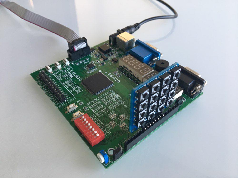
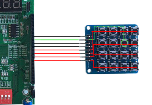
作为我们的董事会,我们选择了Cyclon IV。 因此,我们不得不在硬件描述语言上编写代码。 在学习课程的过程中,我们选择了Verilog。 此外,该大学还拥有用于FPGA的其他模块,例如numpad,因此我们决定在项目中使用它。
在本文中,我们希望分享我们对FPGA和Verilog的知识,还为您提供了一个重复我们项目的教程。
基本设计
我们组成了两个人的小组,并组织了第一次会议。 在那里,我们讨论了基本设计,划分了职责并制定了一个有期限的简短计划。 这就是我们想出的。 我们需要:
- 在Verilog中实施堆栈
- 了解如何使用数字键盘
- 通过FPGA板上的8段显示器实现输出
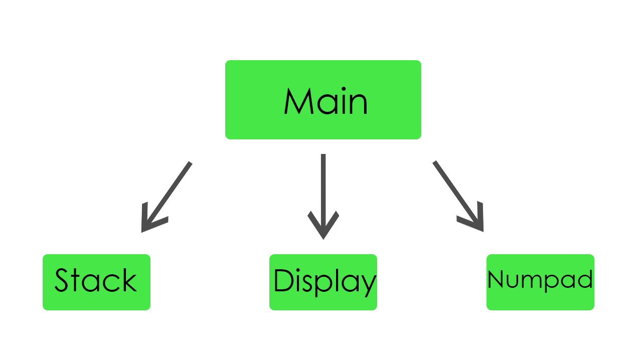
- 制作一个将所有模块连接在一起的主模块
团队的每个成员都选择了自己的模块来编写。 首要任务是实现堆栈,输出和输入。 经确定,我们已开始工作。
叠放
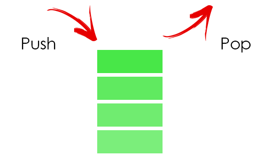
在堆栈中,我们存储所有操作数。 为了存储它们,我们投入了32个字的内存。
堆栈模块代码module stack( //Just 50 MHz clock input clock, //Reset signal input reset, //PUSH operation control signal input push, //POP operation control signal input pop, //SWAP operation control signal input swap, //UPDATE operation control signal input write, //Value to write input [31:0] value, //Top element output [31:0] top, //Second element from stack top output [31:0] next, //Total elements count output [5:0] count, //Stack overflow error output error ); //Stack memory for 32 words reg [31:0] memory [0:31]; //Stack pointer on top element, indexing from 0 reg [5:0] pointer = 0; //First element by default is 0 initial memory[0] = 0; //Top stack element assign top = memory[pointer]; //Second element if such exists, 0 otherwise assign next = pointer == 0 ? 0 : memory[pointer - 1]; //Stack elements count assign count = pointer[4:0] + 1; //Stack overflow signal assign error = pointer[5]; always @(posedge clock) begin //Reseting if (reset) begin memory[0] <= 0; pointer <= 0; end //Remove one element form stack if (pop) pointer <= pointer - 1; //Swaps top and next elements if (swap) begin memory[pointer] <= memory[pointer - 1]; memory[pointer - 1] <= memory[pointer]; end //Update top element if (write) memory[pointer - pop] <= value; //Push new zero element on top if (push) begin pointer <= pointer + 1; //Here pointer is still not updated, so +1 memory[pointer + 1] <= 0; end end endmodule
它只是一个常规堆栈。 如果将一个新值压入该值,它将增加指针并将该值放在堆栈的顶部。 如果一个值从堆栈中弹出,它将减少指针并更新顶部元素。
为了方便起见,我们添加了一个重置按钮,以便有机会在执行时重新启动我们的程序。 另外,为调试添加了捕获堆栈溢出错误的机会。
展示架
在此模块中,我们实现了显示器的所有功能。 它能够动态显示我们的计算结果以及输入值。

这是显示器的代码 module display_bcd ( //Just 50 MHz clock input clock, //Switching hexademical and decimal representations input show_in_hex, //Asserted if something is going wrong, displaing error message input error, //Value to be displayed in binary format input [31:0] value, //Segments of display output [7:0] control, //LEDs of one segment output [7:0] leds ); // ###0### // # # // # # // 5 1 // # # // # # // ###6### // # # // # # // 4 2 // # # ### // # # #7# // ###3### ### //All representation of used symbols parameter D_0 = 8'b00111111; parameter D_1 = 8'b00000110; parameter D_2 = 8'b01011011; parameter D_3 = 8'b01001111; parameter D_4 = 8'b01100110; parameter D_5 = 8'b01101101; parameter D_6 = 8'b01111101; parameter D_7 = 8'b00000111; parameter D_8 = 8'b01111111; parameter D_9 = 8'b01101111; parameter D_DOT = 8'b10000000; parameter D_A = 8'b01110111; parameter D_B = 8'b01111100; parameter D_C = 8'b01011000; parameter D_D = 8'b01011110; parameter D_E = 8'b01111001; parameter D_F = 8'b01110001; parameter D_R = 8'b01010000; parameter D_O = 8'b01011100; parameter D_MINUS = 8'b01000000; parameter D_EMPTY = 8'b00000000; parameter D_E_CODE = 14; parameter D_R_CODE = 16; parameter D_O_CODE = 17; parameter D_MINUS_CODE = 18; parameter D_EMPTY_CODE = 31; //Delay counter, delaying 8192 clock cycles ~ 0.16 ms reg [12:0] counter = 0; //Saved Binary-Coded Decimal reg [31:0] r_bcd; //Number of segment that is active on current iteration reg [2:0] ctrl = 0; //Current digit shown on the current segment reg [4:0] digit; //Asserted for 1 cycle when conversion to Binary-Coded Decimal is done wire converted; //Intermediate Binary-Coded decimal value wire [31:0] bcd; //Decoded number digits wire [31:0] digits; //Number sign wire sign; //Digits from unsigned numbers wire [31:0] unsigned_number; bcd_convert #(32, 8) bcd_convert( .i_Clock(clock), .i_Binary(unsigned_number), .i_Start(1'b1), .o_BCD(bcd), .o_DV(converted)); //Get number sign assign sign = value[31]; //Get unsigned number assign unsigned_number = sign ? -value : value; //Switching final number representation assign digits = show_in_hex ? unsigned_number : r_bcd; //Constolling segments assign control = ~(1 << ctrl); reg [7:0] r_leds; //Controlling LEDs assign leds = ~r_leds; always @(posedge clock) begin case (digit) 0: r_leds <= D_0; 1: r_leds <= D_1; 2: r_leds <= D_2; 3: r_leds <= D_3; 4: r_leds <= D_4; 5: r_leds <= D_5; 6: r_leds <= D_6; 7: r_leds <= D_7; 8: r_leds <= D_8; 9: r_leds <= D_9; 10: r_leds <= D_A; 11: r_leds <= D_B; 12: r_leds <= D_C; 13: r_leds <= D_D; 14: r_leds <= D_E; 15: r_leds <= D_F; 16: r_leds <= D_R; 17: r_leds <= D_O; 18: r_leds <= D_MINUS; default: r_leds <= D_EMPTY; endcase if (error) //Display error message case(ctrl) 0: digit <= D_R_CODE; 1: digit <= D_O_CODE; 2: digit <= D_R_CODE; 3: digit <= D_R_CODE; 4: digit <= D_E_CODE; 5: digit <= D_EMPTY_CODE; 6: digit <= D_EMPTY_CODE; 7: digit <= D_EMPTY_CODE; endcase else //Select current digit case(ctrl) 0: digit <= digits[3:0]; 1: digit <= digits[31:4] ? digits[7:4] : D_EMPTY_CODE; 2: digit <= digits[31:8] ? digits[11:8] : D_EMPTY_CODE; 3: digit <= digits[31:12] ? digits[15:12] : D_EMPTY_CODE; 4: digit <= digits[31:16] ? digits[19:16] : D_EMPTY_CODE; 5: digit <= digits[31:20] ? digits[23:20] : D_EMPTY_CODE; 6: digit <= digits[31:24] ? digits[27:24] : D_EMPTY_CODE; 7: digit <= sign ? D_MINUS_CODE : (digits[31:28] ? digits[31:28] : D_EMPTY_CODE); endcase //Increase current delay counter <= counter + 1; //Delay is done, increase segment number if (counter == 13'b1000000000000) ctrl <= ctrl + 1; //Save converted Binary-Coded Decimal if (converted) r_bcd <= bcd; end endmodule
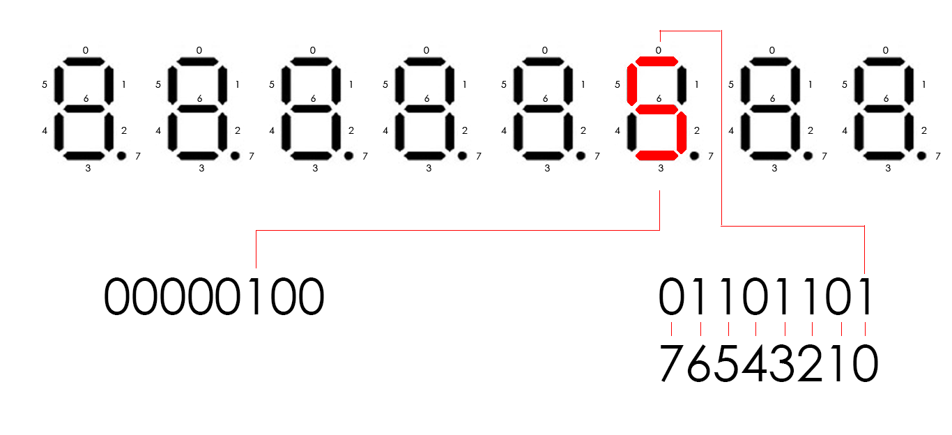
Cyclone IV具有八个八段显示器。 它们由16个引脚控制。 每个显示屏中有八个引脚控制段(我们称其为led),另外八个引脚控制哪个显示屏将处于活动状态(仅称为控件)。 例如,如果我们需要在第三个显示屏上显示数字5,则控件应为00000100,led应为01101101(根据代码中的方案)。 要在不同的显示器上显示几个不同的数字,我们需要定期点亮每个显示器。 因此,每8192个时钟周期,我们将控制输出逻辑左移1位,该输出最初等于00000001。当我们移动它时,我们更改当前要显示的数字。 它发生得如此之快,以至于我们的眼睛看不到变化,因此,我们可以在每个显示器中显示不同的数字。
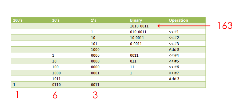
当我们传递给该模块的二进制数时,我们需要以某种方式将其表示为单独的数字。 为此,我们
找到了一个使用双重涉猎算法的模块。 它以二进制数作为输入,并以二进制编码的十进制数(每位4位)返回。
这是它的代码 module bcd_convert #(parameter INPUT_WIDTH, parameter DECIMAL_DIGITS) ( input i_Clock, input [INPUT_WIDTH-1:0] i_Binary, input i_Start, // output [DECIMAL_DIGITS*4-1:0] o_BCD, output o_DV ); parameter s_IDLE = 3'b000; parameter s_SHIFT = 3'b001; parameter s_CHECK_SHIFT_INDEX = 3'b010; parameter s_ADD = 3'b011; parameter s_CHECK_DIGIT_INDEX = 3'b100; parameter s_BCD_DONE = 3'b101; reg [2:0] r_SM_Main = s_IDLE; // The vector that contains the output BCD reg [DECIMAL_DIGITS*4-1:0] r_BCD = 0; // The vector that contains the input binary value being shifted. reg [INPUT_WIDTH-1:0] r_Binary = 0; // Keeps track of which Decimal Digit we are indexing reg [DECIMAL_DIGITS-1:0] r_Digit_Index = 0; // Keeps track of which loop iteration we are on. // Number of loops performed = INPUT_WIDTH reg [7:0] r_Loop_Count = 0; wire [3:0] w_BCD_Digit; reg r_DV = 1'b0; always @(posedge i_Clock) begin case (r_SM_Main) // Stay in this state until i_Start comes along s_IDLE : begin r_DV <= 1'b0; if (i_Start == 1'b1) begin r_Binary <= i_Binary; r_SM_Main <= s_SHIFT; r_BCD <= 0; end else r_SM_Main <= s_IDLE; end // Always shift the BCD Vector until we have shifted all bits through // Shift the most significant bit of r_Binary into r_BCD lowest bit. s_SHIFT : begin r_BCD <= r_BCD << 1; r_BCD[0] <= r_Binary[INPUT_WIDTH-1]; r_Binary <= r_Binary << 1; r_SM_Main <= s_CHECK_SHIFT_INDEX; end // Check if we are done with shifting in r_Binary vector s_CHECK_SHIFT_INDEX : begin if (r_Loop_Count == INPUT_WIDTH-1) begin r_Loop_Count <= 0; r_SM_Main <= s_BCD_DONE; end else begin r_Loop_Count <= r_Loop_Count + 1; r_SM_Main <= s_ADD; end end // Break down each BCD Digit individually. Check them one-by-one to // see if they are greater than 4. If they are, increment by 3. // Put the result back into r_BCD Vector. s_ADD : begin if (w_BCD_Digit > 4) begin r_BCD[(r_Digit_Index*4)+:4] <= w_BCD_Digit + 3; end r_SM_Main <= s_CHECK_DIGIT_INDEX; end // Check if we are done incrementing all of the BCD Digits s_CHECK_DIGIT_INDEX : begin if (r_Digit_Index == DECIMAL_DIGITS-1) begin r_Digit_Index <= 0; r_SM_Main <= s_SHIFT; end else begin r_Digit_Index <= r_Digit_Index + 1; r_SM_Main <= s_ADD; end end s_BCD_DONE : begin r_DV <= 1'b1; r_SM_Main <= s_IDLE; end default : r_SM_Main <= s_IDLE; endcase end // always @ (posedge i_Clock) assign w_BCD_Digit = r_BCD[r_Digit_Index*4 +: 4]; assign o_BCD = r_BCD; assign o_DV = r_DV; endmodule // Binary_to_BCD
该模块使用非常有趣的算法。 它将数字中的所有位一一左移,如果前4位大于十进制的4,则将十进制加3。
数字键
此模块与数字键盘一起使用。 它从numbpad读取值,并将其传递到主模块。 我们有两种状态的键盘。 可以通过按fpga上的按钮之一来切换它们。
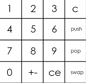
主键盘如下所示:
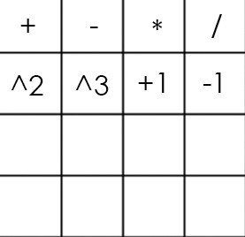
和这样的备用:
小键盘代码 module numpad ( //Just 50 MHz clock input clock, //Alternative keyboard input alt_key, //Alternative keyboard indicator output alt_led, //Numpad rows input [3:0] rows, //Numpad columns output [3:0] columns, //State change description [5:5] - is_changed, [4:4] - keyboard, [3:0] - button output [5:0] value ); // col 0 col 1 col 2 col 3 // // ############################# // # # # # # // # 1(0) # 2(4) # 3(8) # A(12)# row 0 // # # # # # // ############################# // # # # # # // # 4(1) # 5(5) # 6(9) # B(13)# row 1 // # # # # # // ############################# // # # # # # // # 7(2) # 8(6) # 9(10)# C(14)# row 2 // # # # # # // ############################# // # # # # # // # 0(3) # F(7) # E(11)# D(15)# row 3 // # # # # # // ############################# parameter BTN_EMPTY = 6'b000000; //Previous pressed button reg [5:0] prev = 0; //Current pressed button reg [5:0] cur = 0; //Current column number reg [1:0] col = 0; //Counter for delay reg [8:0] counter = 0; //Rows pressed flags reg [3:0] pressed = 0; //Is alternative keyboard reg is_alt = 0; //Alt key on prev clock cycle reg prev_alt_key = 0; //Controlling column assign columns = ~(1 << col); assign alt_led = ~is_alt; always @(posedge clock) begin //Increase counter counter <= counter + 1; //Evaluating alternative keyboard signal if (value != BTN_EMPTY) is_alt <= 0; else is_alt <= (alt_key == 1 && prev_alt_key == 0) ? ~is_alt : is_alt; prev_alt_key <= alt_key; if (counter == 9'b1111111111) begin //Evaluating current button case(~rows) 4'b0001: begin pressed[col] <= 1; cur <= {1'b1, ~is_alt, col, 2'b00}; end 4'b0010: begin pressed[col] <= 1; cur <= {1'b1, ~is_alt, col, 2'b01}; end 4'b0100: begin pressed[col] <= 1; cur <= {1'b1, ~is_alt, col, 2'b10}; end 4'b1000: begin pressed[col] <= 1; cur <= {1'b1, ~is_alt, col, 2'b11}; end default: begin pressed[col] <= 0; cur <= pressed ? cur : BTN_EMPTY; end endcase end //increase column number when counter is 9'011111111, using different edges of counter[8] to let counter pass through zero, to assert wire value if need if (counter == 9'b011111111) begin //Saving previous button every 4 iterations if (&col) prev <= cur; col <= col + 1; end end //Evaluating state change //Comparing current and previous states without keyboard bit assign value = (counter == 9'b000000000 && col == 2'b11 && {prev[5], prev[3:0]} != {cur[5], cur[3:0]}) ? cur : BTN_EMPTY; endmodule
因此,数字键盘是一个包含16个按钮(4行和4列)的方案。 要获得按下的按钮的数量,我们需要4个输出(使其成为列)和4个输入(行)。 我们周期性地将电压传递到每一列,如果按下按钮,电路将关闭,并且某行将作为输入变为真。 列号和行号的组合唯一确定了我们的按钮。
如果在上面的示例中使用主键盘,则将获得数字5作为输入。
主模块
主模块将所有零件连接在一起,并进行实际计算。
这里的主要模块 module main( //Just 50 MHz clock input clock, //Reset signal input reset, //Representation switch input show_in_hex, //Show stack elements count switch input show_count, //Button, switches to operations keyboard input alt_numpad_key, //Alternative keyboard indicator output alt_numpad_led, //Numpad rows and columns input [3:0] numpad_rows, output [3:0] numpad_columns, //Display and display control output [7:0] display_leds, output [7:0] display_control ); // 1 2 3 C // 4 5 6 PUSH // 7 8 9 POP // 0 +- CE SWAP parameter BTN_0 = 6'b110011; parameter BTN_1 = 6'b110000; parameter BTN_2 = 6'b110100; parameter BTN_3 = 6'b111000; parameter BTN_4 = 6'b110001; parameter BTN_5 = 6'b110101; parameter BTN_6 = 6'b111001; parameter BTN_7 = 6'b110010; parameter BTN_8 = 6'b110110; parameter BTN_9 = 6'b111010; parameter BTN_CLEAR_DIGIT = 6'b111100; parameter BTN_PUSH = 6'b111101; parameter BTN_POP = 6'b111110; parameter BTN_SWAP = 6'b111111; parameter BTN_CLEAR_NUMBER = 6'b111011; parameter BTN_UNARY_MINUS = 6'b110111; // + - * / // sqr cbe inc dec parameter BTN_ADDITION = 6'b100000; parameter BTN_SUBTRACTION = 6'b100100; parameter BTN_MULTIPLICATION = 6'b101000; parameter BTN_DIVISION = 6'b101100; parameter BTN_SQUARE = 6'b100001; parameter BTN_CUBE = 6'b100101; parameter BTN_INCREMENT = 6'b101001; parameter BTN_DECREMENT = 6'b101101; //Numpad state wire [5:0] pressed; //Stack elements count wire [5:0] count; //First and second stack elements wire [31:0] top, next; wire stack_error; //Evaluated new value reg [31:0] new_value; //Stack control signals reg write, push, pop, swap; reg arithmetic_error = 0; numpad numpad( .clock (clock), .alt_key (~alt_numpad_key), .alt_led (alt_numpad_led), .rows (numpad_rows), .columns (numpad_columns), .value (pressed) ); stack stack( .clock (clock), .reset (~reset), .push (push), .pop (pop), .swap (swap), .write (write), .value (new_value), .top (top), .next (next), .count (count), .error (stack_error) ); display_bcd display( .clock (clock), .error (stack_error || arithmetic_error), .show_in_hex (show_in_hex), .value (show_count ? count : top), .control (display_control), .leds (display_leds) ); // Division result wire [31:0] res; assign res = ((next[31] ? -next : next) / (top[31] ? -top : top)); always @(posedge clock) begin //Reseting arithmetic error if (~reset) arithmetic_error <= 0; case (pressed) BTN_0: begin write <= 1; new_value <= top * 10; end BTN_1: begin write <= 1; new_value <= top * 10 + (top[31] ? -1 : 1); end BTN_2: begin write <= 1; new_value <= top * 10 + (top[31] ? -2 : 2); end BTN_3: begin write <= 1; new_value <= top * 10 + (top[31] ? -3 : 3); end BTN_4: begin write <= 1; new_value <= top * 10 + (top[31] ? -4 : 4); end BTN_5: begin write <= 1; new_value <= top * 10 + (top[31] ? -5 : 5); end BTN_6: begin write <= 1; new_value <= top * 10 + (top[31] ? -6 : 6); end BTN_7: begin write <= 1; new_value <= top * 10 + (top[31] ? -7 : 7); end BTN_8: begin write <= 1; new_value <= top * 10 + (top[31] ? -8 : 8); end BTN_9: begin write <= 1; new_value <= top * 10 + (top[31] ? -9 : 9); end BTN_CLEAR_DIGIT: begin write <= 1; new_value <= top / 10; end BTN_CLEAR_NUMBER: begin write <= 1; new_value <= 0; end BTN_PUSH: begin push <= 1; end BTN_POP: begin pop <= 1; end BTN_SWAP: begin swap <= 1; end BTN_UNARY_MINUS: begin write <= 1; new_value <= -top; end BTN_ADDITION: begin pop <= 1; write <= 1; new_value <= next + top; end BTN_SUBTRACTION: begin pop <= 1; write <= 1; new_value <= next - top; end BTN_MULTIPLICATION: begin pop <= 1; write <= 1; new_value <= next * top; end BTN_DIVISION: begin pop <= 1; write <= 1; new_value <= (next[31] ^ top[31] ? -res : res); arithmetic_error <= ~(|top); end BTN_SQUARE: begin write <= 1; new_value <= top * top; end BTN_CUBE: begin write <= 1; new_value <= top * top * top; end BTN_INCREMENT: begin write <= 1; new_value <= top + 1; end BTN_DECREMENT: begin write <= 1; new_value <= top - 1; end default: // Nothing usefull is pressed begin write <= 0; push <= 0; pop <= 0; swap <= 0; end endcase end endmodule
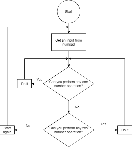
“始终”块包含case语句,该语句根据按下数字键盘的哪个按钮来选择操作。 如果按下了数字按钮,则该数字将到达堆栈顶部。 如果我们需要输入一个多于一个数字的数字,则将堆栈中的最高数字乘以10,然后将该乘积的值移到堆栈的顶部。 如果按下带有操作的按钮,则此操作将应用于堆栈中的前两个数字。
在测试过程中,我们发现了有关Verilog中除法的有趣事情。 由于某些奇怪的原因,如果我们尝试将两个负数相除,则该运算将得出零。 因此,为了修复它,我们必须添加一个分支来显式处理此情况。
结论
这是演示计算器工作原理的视频。 另外,
这是我们项目的github。
对Verilog的研究极大地增加了我们对计算机体系结构的了解。 此外,团队合作帮助我们发展了团队合作的基本软技能。
作者:Fedoseev Kirill,Yuloskov Artem。