大家好! 互联网上存在一个误解,即使用自制的电子设备控制计算机,只需要可以被识别为USB HID设备的专用板即可。 关于Arduino,每个人都在谈论
Arduino Leanardo 。 诸如
键盘和
鼠标之类的流行库,允许您使用微控制器创建鼠标或键盘的仿真,仅适用于一对Arduino Leonardo开发板。
我将讨论如何连接任何Arduino微控制器(例如
Arduino Uno )及其处理程序。 将Processing所基于的Java知识添加到其他所有内容之后,就可以在整个计算机(而不仅仅是其自己的应用程序)的控制下添加项目。 用Java来控制Java中的计算机程序并不是什么秘密,谷歌,我向您保证,您会找到一切。
下载开发环境(IDE)
有许多集成开发环境可用于以纯C语言对微控制器进行编程。 其中,最方便的是Atollic,Eclipse,Keil。
但是,为了本指南的简单性和可访问性,我将使用Arduino IDE编辑器并用Arduino C编写。 您可以从
Arduino官方网站下载这样的编辑器。
也可以从
官方网站下载Procrssing上的编程开发环境。
为了简洁起见,值得注意的是,IDE数据非常相似,因为它们是在同一引擎上编写的。 当创建Arduino时,创始人试图像处理编辑器一样,尽可能简化其代码编辑器。
Arduino的 我们组装电路并编写代码
在此示例中,我将使用Arduino Uno。 一个按钮,一个电位计和一个LED将被连接到它。 因此,我可以输出逻辑0或1。读取逻辑0或1。然后执行
模数转换 (ADC或ADC),根据电位计的位置获取0到1023之间的数字(在Arduino Uno中为10位ADC)。 举例来说,您不需要太多,因为这些是微控制器可以完成的主要功能。
接线图:
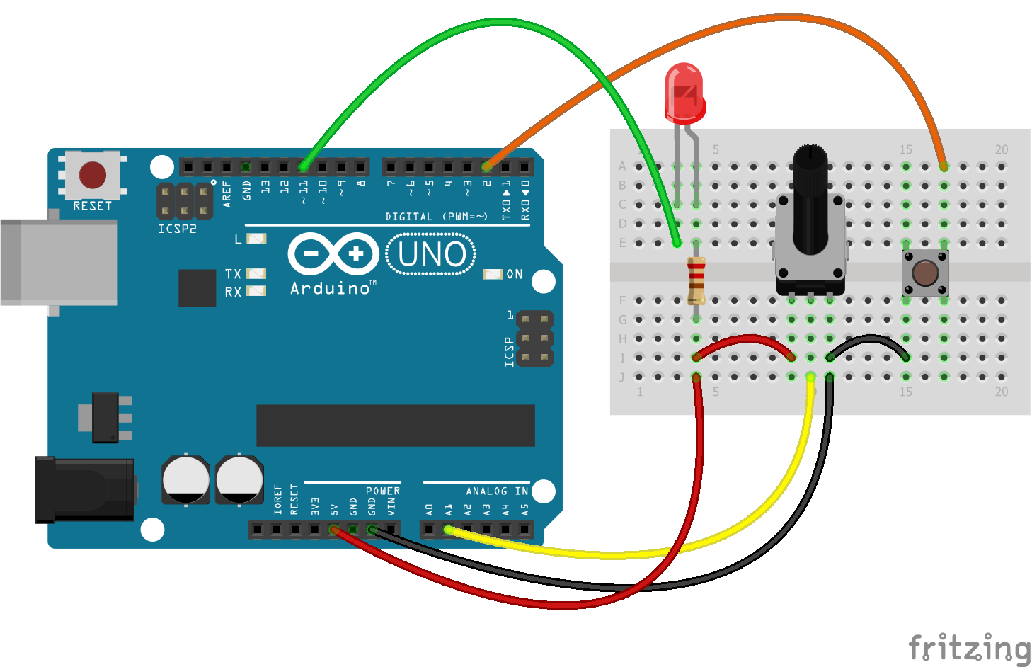
在该图中,阳极LED通过一个阴极(到端子D11)通过一个限流电阻(至少220欧姆,最好为500欧姆)连接到5V。 该按钮关闭接地和引脚D2。 电位计改变引脚A1上的电势。
微控制器的任务如下:如果消息“ LED-H”到达串行接口(串行COM端口),则点亮LED。 如果出现“ LED-L”消息,请熄灭LED。 每250毫秒向串行端口(在这种情况下,向计算机屏幕)发送一条消息“ Pot-”(消息-)以及通过模拟读取针脚A1收到的编号。 当按下按钮时,发送一次消息“按下按钮!”。
这是我对解决此问题的建议(而不是以下示例):
Arduino Uno的固件 #define pinPot A1 #define pinLed 11 #define pinBtn 2 void setup() { pinMode(pinPot, INPUT); pinMode(pinLed, OUTPUT); pinMode(pinBtn, INPUT_PULLUP); Serial.begin(9600); Serial.println("The program starts.\n\n"); } void loop() { /* INITIAL VARIABLES. Segment 1 */ static char potMes[] = "Pot - "; static char btnMes[] = "Button is pressed!"; static char passLight[] = "Led - "; static int passLength = sizeof(passLight) - 1; static int sizepm = sizeof(potMes) - 1; static int sizebtn = sizeof(btnMes) - 1; static bool flagLedState = LOW; static bool flagBtnPress = false; static long int curTime = 0; static const int period = 200; static bool flagEnableRead = false; /* INITIAL VARIABLES. Segment 1 */ /* FUNCTIONS CALL. Segment 2 */ /* * Led is attached to HIGH voltage from one side * And to pin on the other side * By that the inverting logic */ ReadSerialForLed(passLight, passLength, &flagLedState); digitalWrite(pinLed, !flagLedState); /* * Button pin always is pulled to the HIGH voltage * And only when button is pressed - Voltage on pin goes to GROUND * So it is need to invert logic when read pins */ if(!Bounce(pinBtn) && flagBtnPress == false){ for(int i = 0; i < sizebtn; i++){ Serial.write(btnMes[i]); } Serial.print("\n"); flagBtnPress = true; if(!flagEnableRead){ curTime = millis(); flagEnableRead = true; } }else if(Bounce(pinBtn)){ flagBtnPress = false; } /* * Read and send Info "Pot - " + var Only after first press on button * Every 'period'ms */ if(millis() - curTime > period && flagEnableRead){ SendData(pinPot, potMes, sizepm); curTime = millis(); } /* FUNCTIONS CALL. Segment 2 */ } /* * Pot - pin with potentiometer * pMes - Array with message before Pot value * sp - size of potentiometer message */ void SendData(int Pot, char* pMes, int sp){ static int varP[2]; varP[0] = analogRead(Pot); varP[1] = varP[0]/256; // 0 - 3 (256 - 1024) varP[0] = varP[0]%256; // 0 - 255 //Send Message for(int i = 0; i < sp; i++){ Serial.write(char(pMes[i])); } //Send 2 bits of data //Serial.write(varP[0]); //Serial.write(varP[1]); Serial.print(analogRead(Pot)); Serial.print("\n"); } /* * Function, which is reads button pin with the bounce */ bool Bounce(int btn){ if(digitalRead(btn) == true){ delay(15); if(digitalRead(btn) == true){ return true; }else{ return false; } }else{ return false; } } /* * If Message from Serial port, which you read will be the same to passLight * So look at the next symbol after Pass Message. If it is symbol 'H' - make LED to light * If it is 'L' - make LED off. */ void ReadSerialForLed(char *passLight_f, int passLength_f, bool* flagLedState_f){ static char sym; static int cntPass = 0; static bool readyGetLed = LOW; while (Serial.available() > 0) { sym = Serial.read(); if(sym == passLight_f[cntPass] && !readyGetLed){ cntPass++; }else if (!readyGetLed){ cntPass = 0; }else if(readyGetLed){ if(sym == 'H'){ *flagLedState_f = HIGH; }else if(sym == 'L'){ *flagLedState_f = LOW; } } if(cntPass == passLength_f){ readyGetLed = HIGH; } } }
注释:LED通过阳极连接到电源。 这会颠倒LED的状态逻辑,不再有好处。 出于经济原因,该按钮没有与上拉电阻捆绑在一起,因为当引脚初始化为INPUT_PULLUP模式时,Arduino Uno内置了上拉电阻,电路中包括该电阻。
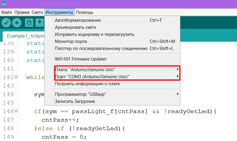
同样在固件中,仅在第一次按下按钮后才发送有关从电位计获取的值的消息!要将固件填充到板上,请不要忘记选择端口和板。
如果您不知道Arduino开发板具有哪个COM端口,请在Windows上转到
控制面板->设备管理器,然后单击“ COM端口”选项卡
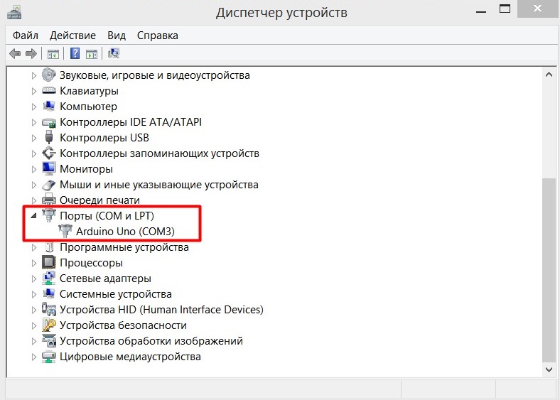
如果您的COM端口未标记为我的端口,则始终可以断开Arduino的连接,然后查看哪个端口消失了。 但是,如果没有人消失并且Arduin根本无法被计算机识别,那么该是时候在Internet上寻找解决方案了。 但是首先要更新驱动程序或更换电路板。
一切正常后,尝试打开端口监视器,然后输入“ Led-H”,“ Led-L”,按下按钮,转动电位计,然后查看屏幕以查看是否正确显示了所有内容。
玩够了-稍微更改代码。
用注释中的代码替换最后一行。
现在,电位计中的值看起来不可读,但是处理程序需要进行这样的操作。
加工中。 我们正在编写一个与微控制器交互的程序
处理程序与微控制器之间通信的本质非常简单。 该编程语言有一个串行库,它允许您接收以
Serial.write();发送的消息
Serial.write(); ,还允许您以
Serial.print();发送消息
Serial.print(); 。 重要的是要注意,发送此类消息后,它将被写入端口缓冲区,这意味着它将被微控制器读取。 因此,我们只需要连接到所需的串行端口并接收/向其发送消息即可。
以下程序将连接串行库,并在编辑器控制台中编写可连接的所有COM端口的列表。
import processing.serial.*; void setup() { String[] port = Serial.list(); for(int i = 0; i < port.length; i++){ print("Port number #" + i + " "); println(Serial.list()[0]); } } void draw() {}
当您将代码写入编辑器并单击“开始”按钮(图片中的箭头1)时,将出现应用程序窗口(2),并且COM端口列表将在控制台中显示(3)。
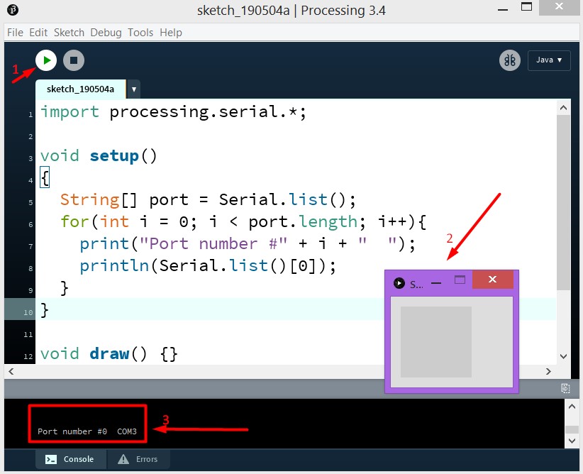
我只有一个这样的COM端口,并且在工作表中(在阵列中)它的编号为0。因此,Serial类的对象是:
Serial port; 创建后,将指定端口列表
port = new Serial(this, Serial.list()[0], 9600);的第一个元素
port = new Serial(this, Serial.list()[0], 9600);更改后倒入Arduin最新固件。 然后编写并运行该程序。 其中每500毫秒将一条消息发送到COM端口,以熄灭或点亮LED。 如果一切操作正确,则在启动应用程序后,LED应当闪烁。
import processing.serial.*; Serial port;
或者这是另一个例子。 用鼠标按钮单击应用程序窗口(尺寸为800x800px)后,LED会更改其状态。
import processing.serial.*; Serial port;
加工中。 功能丰富的应用示例
如果您可以将其称为“太空飞行”,则该基本应用程序将模拟它。 电位计的值改变飞行速度,按下按钮改变飞行方向。 而且,只要在应用程序窗口上单击鼠标按钮,便会更改LED的状态(是的,我没有提出其他更原始的内容)。
我的代码远非完美,请不要以它为例。 这只是一个有效的示例。 他来了
多功能程序示例 import processing.serial.*; Serial port;
结论
我认为有必要写
这篇文章 ,是我从一位程序员
Daniel Shiffman那里挑选了最后一个程序的想法的,他拍摄的视频甚至对于孩子们来说都是关于处理编程的理解(
解决了140多个视觉任务 )。
当我试图弄清楚自己如何进行处理和Arduino通信时,这些站点确实为我提供了帮助:
- developer.alexanderklimov.ru/arduino/processing.php
- arduino-diy.com/arduino-processing-osnovi