ESP32-CAM视频流服务器连接I2C和SPI显示器

Diymore相机的ESP-32 CAM模块

ESP32-CAM视频流服务器


这里是一个使用示例。

您必须首先安装库: Arduino Ide Windows中的 Esp32板 / Arduino Ide Linux和Mac中的Esp32板

详细的设置在本文中。

就我而言,我使用了未注释的AI-THINKER模块
#定义CAMERA_MODEL_AI_THINKER

人脸识别功能不适用于我。 文章中的评论很有帮助。

使用1.02 ESP内核时,面部识别似乎不再起作用(至少对于示例程序而言)。 回滚到1.01内核并使用属于该内核的示例程序,将对其进行“修复”

回滚到库1.01的先前版本后,一切正常。


我有一对I2C 128x64和TFT SPI 128x128显示器

如果您没有CAM模块, 带FIFO的OV7670文章如何将相机连接到显示器。 支持OV2640和OV7670摄像机

在撰写本文时,以下内容对我有用

ESP32相机+ Wifi服务器+ I2C显示屏(AdaFruit)
ESP32相机+ SPI Display 1.44“ TFT 128x128 v1.1(AdaFruit)
ESP32摄像头+ SPI Display 1.8英寸TFT 128 * 160(Espressif库)

WiFi驱动程序与SPI总线冲突。 使用其他库的可能解决方案。 WiFi模块初始化时出现问题。

主要问题是ESP32-CAM模块的自由支脚数量有限。 端口的一部分用于相机,一部分与sd卡并行。 sd卡连接器已安装在板上。 另一个结论(IO4)是LED手电筒。

I2C Display B / W对于从摄像机接收到的图像的实际使用并不特别感兴趣。 TFT彩色和高分辨率。 在它上面,您已经可以看到脸。 在这样的显示器或更高的分辨率上,您可以制作门眼

我马上要说AdaFruit库不是最快的。 我设法每秒显示几帧。 使用低级别的库更有希望。 但是我无法通过显示1.44“ 128x128 SPI V1.1。来获得ESP32_TFT_library。也许不支持ILI9163。我使用1.8” 128 * 160 SPI TFT,设法压缩了大约12 FPS! 友情链接

有几个库的运行速度更快。 但是有些没有移植到esp-32( link ):

4.98秒Adafruit_ST7735
1.71秒ST7735X_kbv
1.30秒PDQ_ST7735

该视频令人印象深刻:


当使用两个端口时,微控制器上的HSPI或VSPI硬件端口之一以及带有ILI9341驱动程序的显示器可以每秒接收30帧( 链接 )。


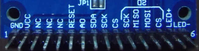
但是正如我之前在ESP32-CAM模块中所说,只有一个SPI是可用的。 它显示在以下PINS上:

IO2-直流(A0)
IO14-时钟
IO15-CS
IO13-MOSI(SDA)
IO12-MISO(输入。未使用)

IO0-BCKL(背光。未使用)
IO16-RST


我尝试的第一个库是AdaFruit SSD1306

I2C 128x64蓝色OLED显示屏


#include <Wire.h> #include <Adafruit_GFX.h> #include <Adafruit_SSD1306.h> #define SCREEN_WIDTH 128 // OLED display width, in pixels #define SCREEN_HEIGHT 64 // OLED display height, in pixels // Declaration for an SSD1306 display connected to I2C (SDA, SCL pins) #define OLED_RESET -1 // Reset pin # (or -1 if sharing Arduino reset pin) Adafruit_SSD1306 display; void init_display(){ pinMode(14,INPUT_PULLUP); pinMode(15,INPUT_PULLUP); Wire.begin(14,15); display = Adafruit_SSD1306(SCREEN_WIDTH, SCREEN_HEIGHT, &Wire, OLED_RESET); if(!display.begin(SSD1306_SWITCHCAPVCC, 0x3C)) { // Address 0x3D for 128x64 Serial.println(F("SSD1306 allocation failed")); for(;;); // Don't proceed, loop forever } .... 

camera_capture()
 #define BACKCOLOR 0x0000 // Black #define PIXELCOLOR 0xFFFF // White #define FRAME_WIDTH 320 #define FRAME_HEIGHT 240 uint16_t pixel_color = 0; esp_err_t camera_capture(){ //acquire a frame camera_fb_t * fb = esp_camera_fb_get(); if (!fb) { ESP_LOGE(TAG, "Camera Capture Failed"); return ESP_FAIL; } int i = 0; for(int y = 0; y < SCREEN_HEIGHT; y++){ for(int x = 0; x < SCREEN_WIDTH; x++){ i = y * FRAME_WIDTH + x; // FRAMESIZE_QVGA // 320x240 char ch = (char)fb->buf[i]; if (ch > 128) pixel_color = WHITE; else pixel_color = BLACK; // Draw a single pixel in white display.drawPixel(x, y, pixel_color); } } display.display(); //return the frame buffer back to the driver for reuse esp_camera_fb_return(fb); Serial.println("Capture frame ok."); return ESP_OK; } 


在esp32中工作时,使用软件I2C仿真。 涉及IO14和IO15。 几乎可以使用任何可用端口,而不使用H / W总线。

如何连接单色0.96“ i2c OLED显示器 。您需要注意I2C总线上的显示地址。在这种情况下,为0x3C

SPI Display 1.8“ TFT 128 * 160乐鑫库


接线图:

IO2-A0
IO14-SCK
IO15-CS
IO13-SDA
IO16-重置


板上还有一个SD卡读卡器

IO配置:

 // Configuration for other boards, set the correct values for the display used //---------------------------------------------------------------------------- #define DISP_COLOR_BITS_24 0x66 //#define DISP_COLOR_BITS_16 0x55 // Do not use! // ############################################# // ### Set to 1 for some displays, ### // for example the one on ESP-WROWER-KIT ### // ############################################# #define TFT_INVERT_ROTATION 0 #define TFT_INVERT_ROTATION1 0 // ################################################ // ### SET TO 0X00 FOR DISPLAYS WITH RGB MATRIX ### // ### SET TO 0X08 FOR DISPLAYS WITH BGR MATRIX ### // ### For ESP-WROWER-KIT set to 0x00 ### // ################################################ #define TFT_RGB_BGR 0x08 // ############################################################## // ### Define ESP32 SPI pins to which the display is attached ### // ############################################################## // The pins configured here are the native spi pins for HSPI interface // Any other valid pin combination can be used #define PIN_NUM_MISO 12 // SPI MISO #define PIN_NUM_MOSI 13 // SPI MOSI #define PIN_NUM_CLK 14 // SPI CLOCK pin #define PIN_NUM_CS 15 // Display CS pin #define PIN_NUM_DC 2 // Display command/data pin #define PIN_NUM_TCS 0 // Touch screen CS pin (NOT used if USE_TOUCH=0) // -------------------------------------------------------------- // ** Set Reset and Backlight pins to 0 if not used ! // ** If you want to use them, set them to some valid GPIO number #define PIN_NUM_RST 0 // GPIO used for RESET control #define PIN_NUM_BCKL 0 // GPIO used for backlight control #define PIN_BCKL_ON 0 // GPIO value for backlight ON #define PIN_BCKL_OFF 1 // GPIO value for backlight OFF // -------------------------------------------------------------- // ####################################################### // Set this to 1 if you want to use touch screen functions // ####################################################### #define USE_TOUCH TOUCH_TYPE_NONE // ####################################################### // ####################################################################### // Default display width (smaller dimension) and height (larger dimension) // ####################################################################### #define DEFAULT_TFT_DISPLAY_WIDTH 128 #define DEFAULT_TFT_DISPLAY_HEIGHT 160 // ####################################################################### #define DEFAULT_GAMMA_CURVE 0 #define DEFAULT_SPI_CLOCK 32000000 #define DEFAULT_DISP_TYPE DISP_TYPE_ST7735B //---------------------------------------------------------------------------- #define TFT_INVERT_ROTATION 0 #define TFT_INVERT_ROTATION1 1 #define TFT_INVERT_ROTATION2 0 

Espressif安装环境和开发环境。 有关如何执行此操作的详细说明。

安装 。 需要进行两个更正才能组装库。

生成文件:

 + CFLAGS += -Wno-error=tautological-compare \ + -Wno-implicit-fallthrough \ + -Wno-implicit-function-declaration 

组件/ tft / tftspi.c:

 + #include "driver/gpio.h 

补丁

然后安装ESP32 Camera Driver

配置:

# $ HOME / esp / esp-idf / export.sh
#idf.py menuconfig


允许访问USB端口以进行固件和监视:

#sudo chmod 777 /开发/ ttyUSB0

我们收集并填写:

#make -j4 && make flash

通过使用send_data方法写入数据包可实现12FPS。 记录不是逐像素进行的,而是整行等于屏幕的宽度:

 esp_err_t camera_capture(){ uint32_t tstart, t1, t2; tstart = clock(); //acquire a frame camera_fb_t * fb = esp_camera_fb_get(); if (!fb) { printf("Camera Capture Failed\n"); return ESP_FAIL; } t1 = clock() - tstart; printf("Capture camera time: %u ms\r\n", t1); int i = 0, bufPos = 0; uint8_t hb, lb; color_t color; color_t *color_line = heap_caps_malloc(_width*3, MALLOC_CAP_DMA); tstart = clock(); for(int y = 0; y < _height; y++) { bufPos = 0; for(int x = 0; x < _width; x++) { i = (y * FRAME_WIDTH + x) << 1; hb = fb->buf[i] ; lb = fb->buf[i + 1]; color.r = (lb & 0x1F) << 3; color.g = (hb & 0x07) << 5 | (lb & 0xE0) >> 3; color.b = hb & 0xF8; color_line[bufPos] = color; bufPos++; // TFT_drawPixel(0, 0, color, 1); } disp_select(); send_data(0, y, _width-1, y, _width, color_line); wait_trans_finish(1); disp_deselect(); } free(color_line); t1 = clock() - tstart; printf("Send buffer time: %u ms\r\n", t1); esp_camera_fb_return(fb); printf("Capture frame ok.\n"); return ESP_OK; } 

相机配置
 // #if defined(CAMERA_MODEL_AI_THINKER) #define PWDN_GPIO_NUM 32 #define RESET_GPIO_NUM -1 #define XCLK_GPIO_NUM 0 #define SIOD_GPIO_NUM 26 #define SIOC_GPIO_NUM 27 #define Y9_GPIO_NUM 35 #define Y8_GPIO_NUM 34 #define Y7_GPIO_NUM 39 #define Y6_GPIO_NUM 36 #define Y5_GPIO_NUM 21 #define Y4_GPIO_NUM 19 #define Y3_GPIO_NUM 18 #define Y2_GPIO_NUM 5 #define VSYNC_GPIO_NUM 25 #define HREF_GPIO_NUM 23 #define PCLK_GPIO_NUM 22 void camera_init_(){ camera_config_t config; config.ledc_channel = LEDC_CHANNEL_0; config.ledc_timer = LEDC_TIMER_0; config.pin_d0 = Y2_GPIO_NUM; config.pin_d1 = Y3_GPIO_NUM; config.pin_d2 = Y4_GPIO_NUM; config.pin_d3 = Y5_GPIO_NUM; config.pin_d4 = Y6_GPIO_NUM; config.pin_d5 = Y7_GPIO_NUM; config.pin_d6 = Y8_GPIO_NUM; config.pin_d7 = Y9_GPIO_NUM; config.pin_xclk = XCLK_GPIO_NUM; config.pin_pclk = PCLK_GPIO_NUM; config.pin_vsync = VSYNC_GPIO_NUM; config.pin_href = HREF_GPIO_NUM; config.pin_sscb_sda = SIOD_GPIO_NUM; config.pin_sscb_scl = SIOC_GPIO_NUM; config.pin_pwdn = PWDN_GPIO_NUM; config.pin_reset = RESET_GPIO_NUM; config.xclk_freq_hz = 20000000; config.fb_count = 2; // for display config.frame_size = FRAMESIZE_QVGA; config.pixel_format = PIXFORMAT_RGB565; // camera init esp_err_t err = esp_camera_init(&config); if (err != ESP_OK) { printf("Camera init failed with error 0x%x", err); return; } printf("Camera init OK\n"); } 


要点

FRAME_WIDTH是QVGA的320像素的帧宽度

 config.frame_size = FRAMESIZE_QVGA; // 320x240 

实际上,我们在显示窗口中以全帧形式看到128 * 160

使用一个摄像机缓冲区记录配置日志(config.fb_count = 1)
拍摄相机时间:32毫秒
发送缓冲时间:47毫秒
捕获框架。

结果
1000 /(32 + 47)= 12.65帧

记录两个便携式摄像机缓冲区的配置(config.fb_count = 2)
拍摄相机时间:39毫秒

发送缓冲时间:63毫秒

捕获框架。
拍摄相机时间:0毫秒

发送缓冲时间:59毫秒

捕获框架。
拍摄相机时间:0毫秒

发送缓冲时间:34毫秒

捕获框架。
拍摄相机时间:40毫秒

发送缓冲时间:64 ms

捕获框架。
拍摄相机时间:0毫秒

发送缓冲时间:59毫秒

捕获框架。
拍摄相机时间:0毫秒

发送缓冲时间:34毫秒

捕获框架。
拍摄相机时间:40毫秒

发送缓冲时间:63毫秒

捕获框架。
拍摄相机时间:0毫秒

发送缓冲时间:60毫秒

捕获框架。
拍摄相机时间:0毫秒

发送缓冲时间:34毫秒

捕获框架。
拍摄相机时间:39毫秒

发送缓冲时间:63毫秒

捕获框架。
拍摄相机时间:0毫秒

发送缓冲时间:60毫秒

捕获框架。
拍摄相机时间:1毫秒

发送缓冲时间:34毫秒

捕获框架。
拍摄相机时间:40毫秒

发送缓冲时间:63毫秒

捕获框架。
拍摄相机时间:0毫秒

发送缓冲时间:60毫秒

捕获框架。
拍摄相机时间:0毫秒

发送缓冲时间:34毫秒

捕获框架。
拍摄相机时间:40毫秒

发送缓冲时间:63毫秒

捕获框架。
拍摄相机时间:0毫秒

发送缓冲时间:59毫秒

捕获框架。
拍摄相机时间:0毫秒

发送缓冲时间:35毫秒

捕获框架。

由于使用了摄录一体机的第二个缓冲区,因此可以立即获得某些周期的缓冲区。 首先,使用不到一个缓冲区就可以获得完整的循环,但是这一次“继续”进行。 周期之间的间隔是浮动的。

几次我在日志中发现“触发了欠压检测器”,因此我关闭了检测器。 因为起初我从3.3V ESP32-CAM引脚提供了背光显示

 #include "soc/rtc_cntl_reg.h" ... WRITE_PERI_REG(RTC_CNTL_BROWN_OUT_REG, 0); //disable brownout detector 

结论


ESP32低成本功能模块。 对于板的CAM版本中已实现的端口,缺乏结论性的灾难性结论,因此,如果您确实需要相机,请选择CAM版本。

Source: https://habr.com/ru/post/zh-CN463157/


All Articles